MC3P60V50A – 3KW Motor Controller

This will be work in progress for another week at least. I have routed the right side of DRV8301, but I have the left side + MCU left. I initially started with a STM32F303CB, but decided to move up to a STM32F405RG. Current size is ca 100mm x 25mm and components only on top side. I have received the 60V/160A MOSFET’s I plan to use.

This is a dedicated 3-Phase controller. I have so far added JST connectors for SWD, CAN, RS485 and 6 sensor inputs. I will add bias and jumpers for RS485 top-left + I would like to add a USB connector, but I probably need to sacrify CAN or RS485 to do that.

Compared to MC4X24V15A this is 20 mm longer and 15mm thinner design with components on the top side only – but, let me finish routing before I brag to much – I do however think that worst case here is another 5mm in thickness due to density on left side – lets see. 

I will solder up a new MC4X24V15A to complete testing and start writing actual code. I have received the MOSFET’s. The old board is stil working, but reduced to 12V due to some destructed lanes that proved difficult to repair. But, that is ok for algorithm work on lower effects.

Size of things

This show 3 components on a 3D model. The one to left is a 0603 package, and if you have any idea of how small that is then you also see the size of INA210 in the middle. INA194 is SO-23/5 which is “easy”. I consider 0603 easy as well, but 6 pins on that INA210 was a bit on the edge.

I have never tried a 0402 component and based on my experience with 0603 I don’t think I want to either – not with manual assembly.

L293 – 3 Phase Arduino Motor Controller

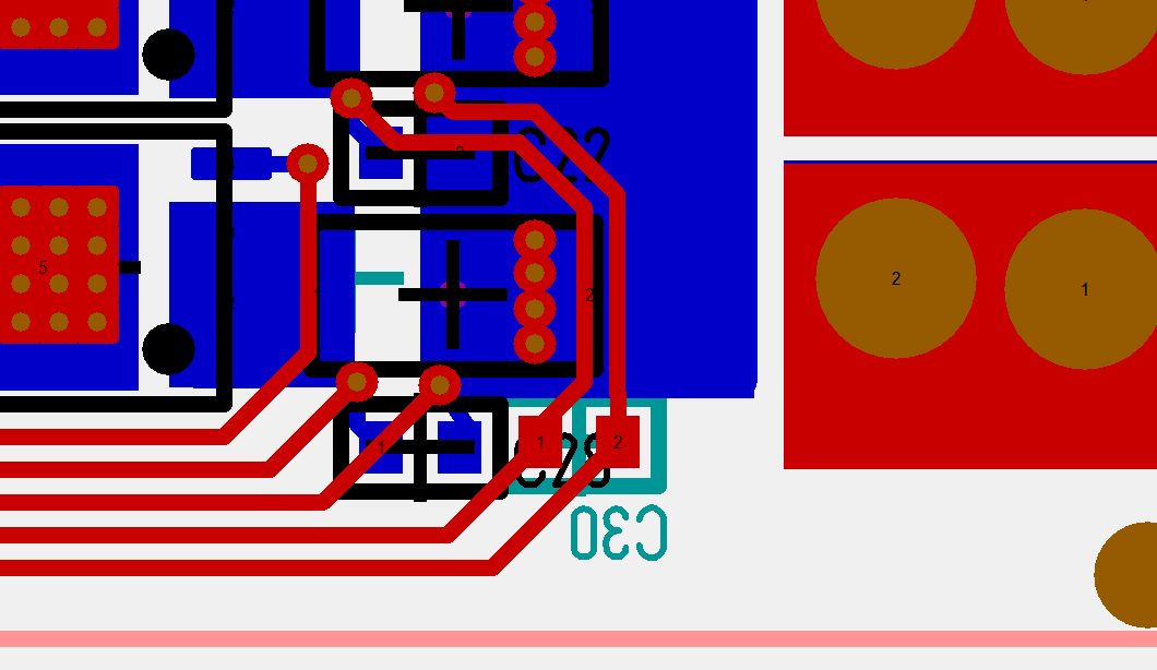
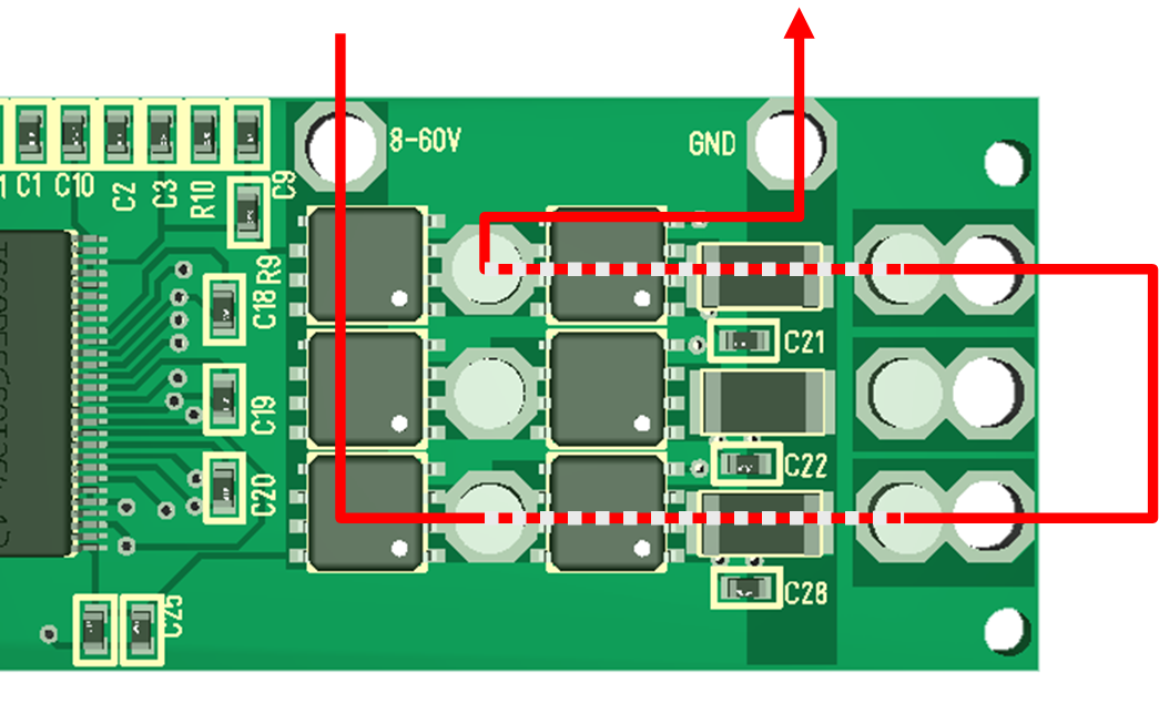
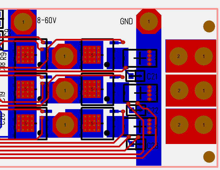
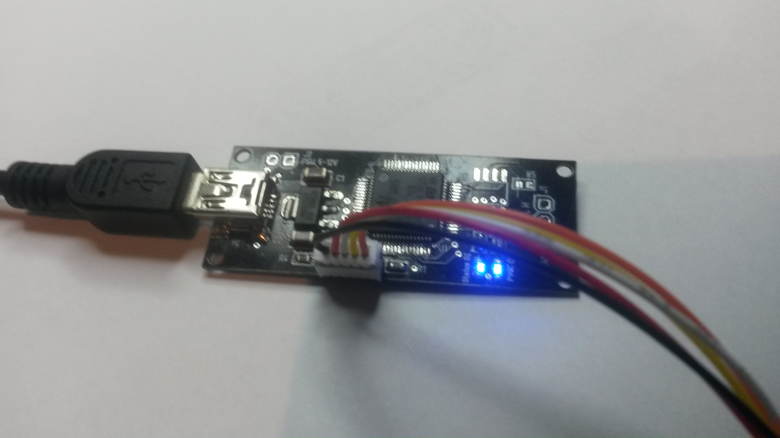
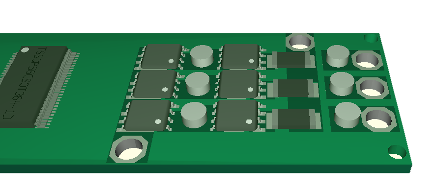
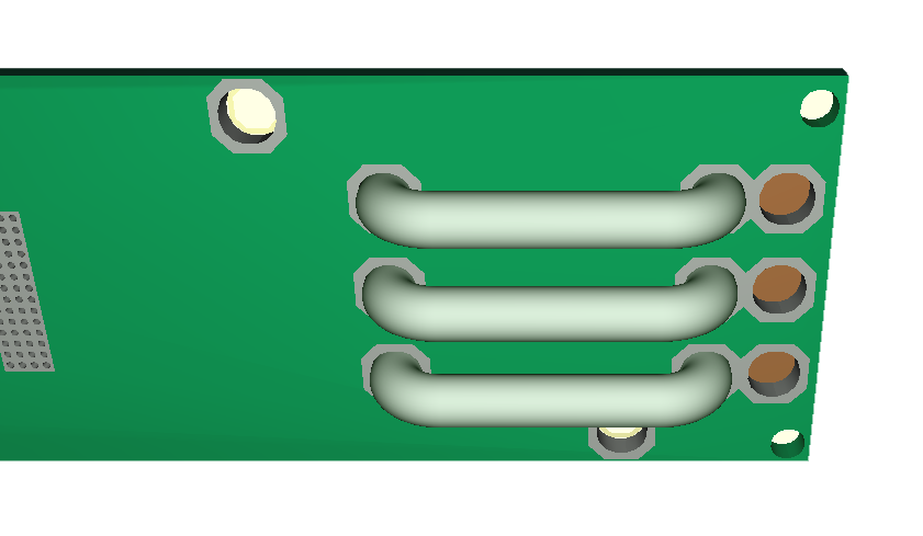
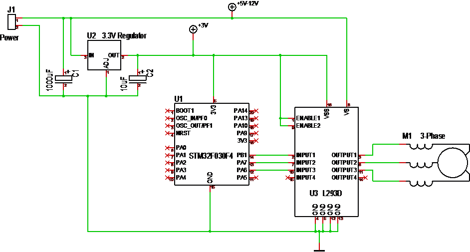
This little circuit is a 5-36V 3-Phase motor driver. In this case I use 3 channels of a classic L293D to output to a small 3-phase motor and run it using a Trapzoidal motor algorithm. I am running L293 on 3.3V, but it will work better on 5V and an Arduino is better for this experiment. MCU’s like 8-bit AVR and PIC have been used for 3-phase controllers for years, and as this example will demonstrate you don’t need much to spin a motor using Trapsoidal or Sinusoidal algorithm’s.

The concept of Trapzoidal is that you pulse each phase in sequence A->B->C and repeat it to turn the motor in one direction. To reverse you do C->B->A. How fast you spin is now your speed as you drive the coils directly by pulsing. You will discover that if you go to fast the motor will not start and if you go to slow t will bump in steps.

To improve the algorithm we take advantage of the 3 coild. Using A create one position, using A+B creates a 2nd and using B creates a 3rd. So we now output PWM to A->A+B->B->B+C->C->C+A and repeat it. You now have the 6 steps of a Trapzoidal algorithm.

            if(forward)
            {
                  Set3Phase(1,1,0,sOn,sOff,speed);
                  Set3Phase(1,0,0,sOn,sOff,speed);
                  Set3Phase(1,0,1,sOn,sOff,speed);
                  Set3Phase(0,0,1,sOn,sOff,speed);
                  Set3Phase(0,1,1,sOn,sOff,speed);
                  Set3Phase(0,1,0,sOn,sOff,speed);
            }
            else
            {
                  Set3Phase(0,1,0,sOn,sOff,speed);
                  Set3Phase(0,1,1,sOn,sOff,speed);
                  Set3Phase(0,0,1,sOn,sOff,speed);
                  Set3Phase(1,0,1,sOn,sOff,speed);
                  Set3Phase(1,0,0,sOn,sOff,speed);
                  Set3Phase(1,1,0,sOn,sOff,speed);
            }

If you drive the motor directly you need to send a PWM with sufficient length & torque to move the rotor. This will vary with input voltage, but start at 5V with 50% PWM duty. I had to use 100% at 5V and 30% at 12V. Once the motor is started you can accelerate it up into speeds.

The drawback with this algorithm is that it has no knowledge of rotor position so the vector we output might be wrong. In most cases it will need ca 1 turn to sync with the rotor.

Trapzoidal algorithm is not used these days because you can as well use the Sinusoidal algorithm as minimum. But, a simple trapzoidal algorithm can be implemented in logic without a MCU involved.

The Sinusoidal version is based on a Sinus curve. While we on Trapsoidal have 6 steps we will on sinusoidal vary PWM duty on A,B and C to create as as many steps as we want.

Keep in mind that a coil act as a filter, so with 5V and 50% duty I am actually outputting 2.5V. By changing PWM duty I can create several more steps to make the motor move smoother. This require a bit more math, but most MCU’s can manage a pre-calculated lookup table etc.

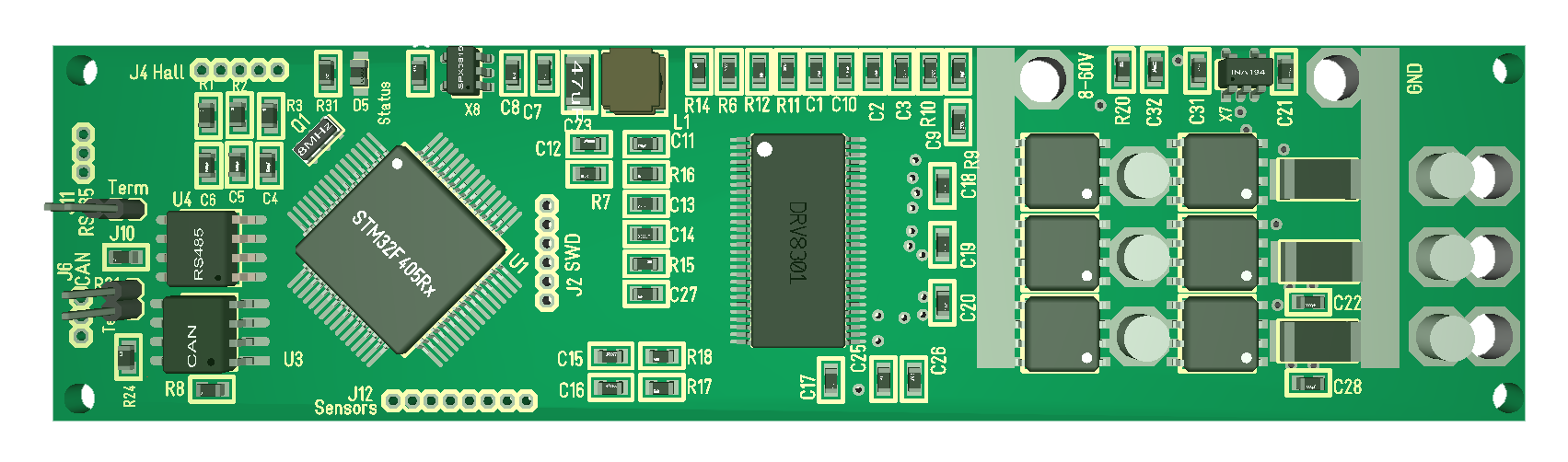
The remaining question is however – where is the rotor? To know this we need to add a sensor. In fact we have 4 different ones that can be used for measuring speed and rotor position.

  • BEMF. As we output voltage on 2 coils we can measure the feedback on the 3rd. I have never tried this, but the feedback should tell us something about position.
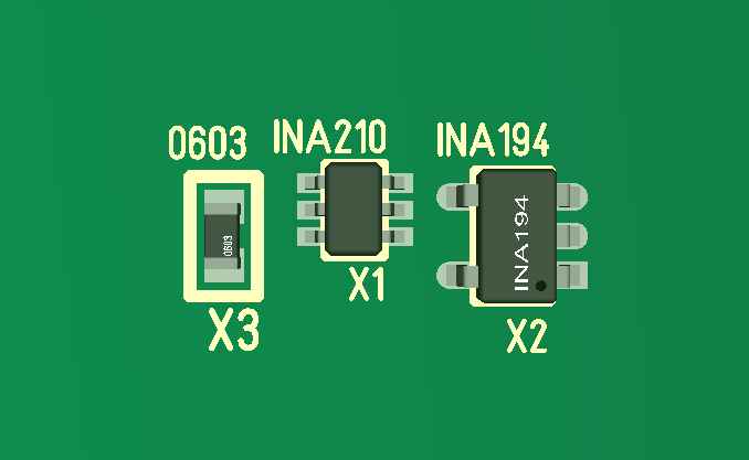
  • Current Sensor means you add a low- or high-side current sensor on each phase and you can use them to calculate rotor position.
  • Hall Sensor will give a position signature based on magnetic fields.
  • Resolver will give you position.

Knowing the position you can use this to look-up the next entry in Trapsoidal or Sinusoidal algorithm. But, you could also do more advanced math to calculate a perfect 90 Degree vector – this is the FOC algorithm that requires a M3 or faster to be possible.

A lot of my articles dig into the more complex sides of running a 3-phase motor and might give the impression that this is more difficult than it is. So, I advice you to get an Arduino (or whatever), connect a L293 and start spinning a small 5-12V 3-phase motor to see how easy this actually is.

INA194 – 80V Current Sensor

INA210 that I used earlier is only rated for 26V, and it is a 6-pin extremely small package that was a Challenge to get soldered. I have 9 more chips to destroy before I let INA210 rest, but I will not continue with this for 3 reasons (1) size of a 6 pin package and marking made it difficult, (2) 26V is to limit and (3) I finally discovered INA193 to 198 that is SOT-23 based (larger) and support 80V.

Texas Instruments have a large range of current sensors and the series 193 to 198 is sensors With fixed gain of 20, 50 and 100. The difference between packages are pin layout, but they are all SO-23/5. This is small, but my main struggle With INA210 was to identify pin 1. SO-23 is a little larger and that makes a difference.

Input Voltage on these are 2.7V to 18V, but sensor input support -16 to 80V. No external Components are required, but some fltering is recommended. Prices are in the region of 1.7.- USD for samples – 0.8 USD for 500 volumes. So what gain do I want?

50A * 0.001R = 0,05V and I need a 3Vich so gain 60 – or 50 which is INA194 should be workable. Using a 12 bit ADC over 3V I get a sensitivity of 3/4096, meaning the value 1 represent 0.0007V. Using a 0.001R shunt that is 0.7A direct sensitivity – amplified with 50X we should have 0,014mA sensitivity giving a range 14mA to 50A – in theory.

The alternative is that I double the Shunt and use 20X gain – that will give a 17mA sensitivity, but should be more reliable as we get a better signal/noise situation. The challenge is the effect over the shunt. 50A is 2.5W on a 0.001R and 5W on a 0.002R. I hope to get away with 2.5W since it should be divided by 3, but I need bigger shunts for 5W. This is however a workable improvement for a 15A design where 15A should be 0,45W over a 0,002Ohm.

This is the 3rd reason I want the 3rd sensor on the 50A design – to be able to test current sensors and what I can achieve. Using 50A I need to worry about effect usage, using <50mA I need to worry about signal/noise – so whatever I will be a trade-off. DRV8303 help in the sense that it has a PGA (Programmable Gain Amplifier). You can also get stand-alone versions for that, but they require I2C or SPI. And adding more Gain will not improve Signal/Noise factor or change the size of the shunt.

INA193-195 are a bit expensive, but they are worth it if they do the job. I ordered 10x from Arrow for 18.- USD – they will be here in ca 5 days.

Current Sensor Concerns

Current sensors are a challenge due to noise as you need to grab PWM signals. I am doing 2 things here:

  1. I am grabbing both current sensing and ground from the same place. directly on each side of the shunt. The EDA I use will try to include this in a ground plane, so I have to make sure it stay as a separate signals to avoid all kind of funny ground signal noise.
  2. I am adding a spare – not stuffed – capacitor on the back side for the signal that need to pass the lower PWM. I am not sure I need this, but I had the space and it gives me an option to move the filter cap to after the PWM passing to see if it makes a difference.

Current sensors are very exposed for noise and this is one place where I seriously could have needed 6 layers to shield these signals better. As this signals arrive on DRV8301 they will be amplified and used for trip alarms. On the output to the MCU we add a 2nd filter to work on noise.

If we short-cut a phase I also need to cut the motor fast – very fast. I can’t stop the first PWM as we need that to detect that a phase is shorted, so how many PWM output’s can we survive with Rt and Rs being our only resistance (2.9mOhm all together)?

Answer : I don’t know! If you do that math with 60V you will realize that a shorted pulse is an insane 20.690 Ampere. Assuming you have 10% PWM duty that is still some 2000Ampere that instantly will fry a MOSFET and Shunt, so to have any chance we will need to react on the 1st PWM and have cut the MOSFET’s on the 2nd. What will help us here is that the PSU that feed us have a limitation and analogue trip. The worst scenario is actually if we are connected to a battery because some batteries will actually support these insane pulses.

Back to the filter – this is why you might not want a hardware filter at all because it delays this signal. If you filter in SW you can still respond to a single, insane pulse, but that short-cut is also almost 21V over the shunt so I am happy DRV8301 is in the front-line here.

DRV8301 do actually have an analogue/logic trip, meaning that if we short-cut we also cut PWM signals based on a different response speed than we can achieve in SW. But, what about the 3rd phase?

This is one of many reasons I would like a current sensor on the 3rd phase. The other reason is that it gives me a capability to measure signal error on current sensing. I also have ca 15 x 5mm space between 60V and GND so I could add sensor logic here and if I move the PCB 1mm up I should also have extra space to route that sensor pass the 60V connector – some of the reference diagrams for DRV8301 show a discrete 3rd current sensor, so will look into that. I will add the 3rd if I can, but focus on this experiment is size and components on top layers only.

60V/50A BLDC PCB Routing

One of the main concern if you want to get 50A out is the current path and making sure it support 50A. The line in red show an actual example path that will have to support this. The entire driver area is only 40mm x 25mm.

60V in using top PCB lane down, over high side MOSFET, out through wire and back in through next channel and out through low side MOSFET and current shunt to GND. The weak link here is that I need 1mm x 4mm lanes to support 50A, so if I cover the lanes with solder tin it should be doable. If not I will start getting into problems around 10+ Ampere.

Looking at this design I can instantly see that I need a few more mm to create a solder lane on 60V and GND. But, after this mod I should actually stand a chance on currents.

Looking at signals I am not sure if I want to create interface between MCU and Gate Driver, or between Gate Driver and MOSFET. Assuming I do the last I will need the following:

  • 8-60V
  • 6 x PWM Signals
  • 3 x PWM out signals
  • 6 x current sense signals.
  • In addition I should get 1.3 x temperature sensors for the MOSFET’s.

This pic show the actual routing of the driver. Notice the hole pads on the MOSFET’s, the short, effective lanes, but also the 4 tracks at bottom. The bottom tracks are current sensors and I grab both GND and Sensor at the same spot. This is quite important because you will get into funny ground signals if you grabbed ground from somewhere else – more convenient. I really should have had more layers to protect these signals from noise, but we will test. Looking at the PCB I realize I have the Space to move the GND hole to bottom just to make sure that 60V and GND wires are far apart to create less noise. But, I also like the idea of having them far away from current sensor tracks. This pic does not show the ground plane.

As for effect I calculate 4.75W for 50A and 1.9mOhm. As this is split on 3 transistors I actually hope to get away without heat-sinks. The same goes for the Shunt. 0.001R will be 2.5W, but again as this is 3-phase it should be split by 3. As mentioned the MOSFET’s support 160A, but I stand no chanse of supporting that. This will regardless be interesting to test, but I have a bit of work left before I get there. This controller might be my x-mas fun.


STM32F105 Limitation

Bummer – just received my USB/CAN adapter PCB’s and realized that they are wasted. Soldered one up, but as I intended to activate USB I realized 2 things: (1) HSI can only be clocked up to 36Mhz and (2) USB will only work with HSE (External Crystal).

I have these small Murrata ceramic Crystals that take no space, so not sure why I did not just added them. I obviously need to order new PCB’s, but I have other dev cards I can use for USB testing. This error could have been avoided if I had checked with CubeMX first.

The New SWD port with micro JST works fine. I am just using a cable to the old adapter.

60V/50A BLDC Stick

This is a mock up of routing 50A out from a small PCB with 2 layers. I use 3mm wire as “high side” shunt on bottom to get to the right where I can connect 3-Phase. This leaves MOSFET’s and current shunt’s on top. I also get heat-sink if needed on top covering both MOSFET and Shunt’s. I should not need heat-sink up to 25A, but I will need a small heat sink to get rid of ca 8W in total over MOSFET’s and Shunt’s at 50A. I might very well have to limit this to 40A.

I will need between 90-20mm to 100 to 25mm to route this BLDC controller, but this is a 60V 50A design delivering up to 3000W.

MOSFET’s are 1.9mOhm so 50 will dissipate 4.75W in total in DC mode, but since this is a 3-phase we will in average have 16.7A per MOSFET which is 0,5W. This should actually be within what we can dissipate without heat-sink and these MOSFET’s have 400A pulse drain and 160A limit, so I could be getting anything between 30A to 100A++ out of this design. 100A/3 over 1.9mOhm is in theory 2W – which is doable – not sure. At this point I just need to test and see where the weakest link is. 3mm wire is sufficient for 50A, but I will need to increase this for 100A.

How do I test a 50A to 100A controller? First challenge is actually to buy a motor that will cost me ca 200.- USD. The second is to build a PSU. My largest PSU is 50V/20A, but I can test 60V and Max A independent using a 12V LIPO for the later.

I better get a fire distinguisher prepared before I test this.

Another Win on this design is that the left side with MCU, DRV8301 and Communication easily can be separated out as the controller board for even larger Motor Controllers. And no worries – I am still keen on making a sized Down Controller for 15A and 2-3A.