MC4X24V becomes MC4X60V

The 40V or 30V or 26V – ouch limits have always annoyed me, so with new MOSFET’s, current sensors and PSU I change to 60V design. Making Space for SOP Advance I can always use SOP and 30V MOSFET’s anyway.

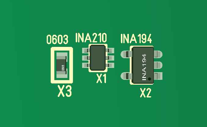
I finally found several temperature sensors in SOT23 package, so I ordered 2 different ones to test. SOT23 with no passive components means I should be able to sneak these in between the MOSFET’s – add 2 on MC4X.. and 1 one MC3P..

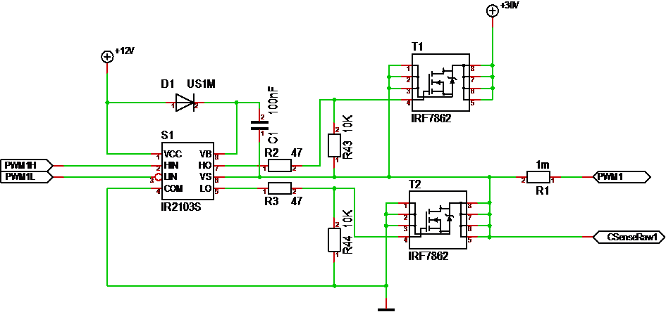
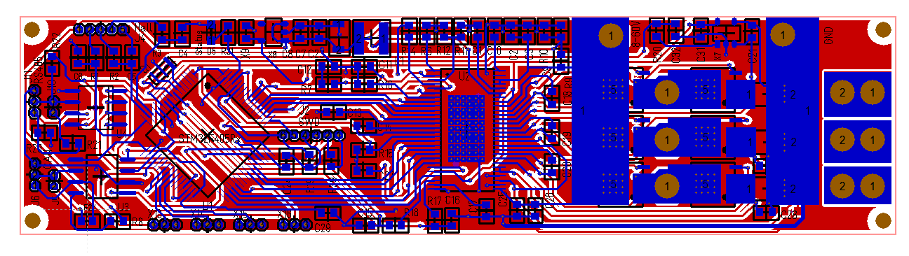
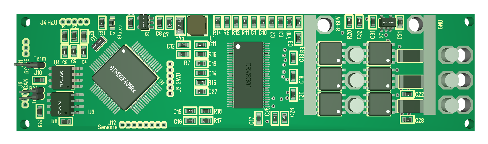
Testing MC4X I realize that I probably need to re-route revision 1.1 from scratch. I need a minimum of 1mm extra space between channels for SOP Advance package options + I want JST connectors on each channel rather than 1.27 pitch headers. I need space for INA194 as well as the temperature sensors. I also want 1000uF on the controller directly etc.

On the present controller I tried for a more narrow board and ended up adding space. Truth is that MC3P end up being a smaller design with components only on top side – I don’t think I can or want top-side only on MC4X, but I would like 100 x 40mm format due to the availability of heat-sink’s in that size. So if I include capacitors on that size it will be good.

I am not going to bother with higher currents on this solution as it would require to much. I got the 3P design for higher currents and 3-phase motors even if I realize that my first routing here also need to be modified.

It will be a bit of work before I order either MC4X or MC3P as both needs changes, but it is worth it. I am actually impressed with MC4X testing so far despite a few set-backs. I expected PCB lanes to be a problem and not dodgy MOSFET’s, so things are looking very good for a 15A design. With new MOSFET’s I might very well upgrade current ratings, but that is not an objective right now. I will also be using 3X-, 4X- and 3P-Controller as terminology from here. Writing the full names are a bit confusing and at present I only want to continue with 3 controllers. Others do small, insane 3-phase drivers better than me, so I focus on actuator Controllers. I can never compete With the smallest size using 2-layers anyway – but, it is real fun to see what I can achieve.

Improved PWM Driver Circuit

This shows my new driver circuit. I added R43 and R44 as weal pulldown’s to avoid that the MOSFET start leading by accident at power up. If I get space limitations I will rather remove R1 and R2. This will make it safer to put power on a Motor Controller in case the Gate Driver is disconnected or broken.

MC4X24V15A Motor Controller Upgrade

I still want to test more with rev 1.0 of MC4X24V15A, but I am also planning an upgrade. I initially drew a rev 1.1 using 78M12, but I will replace LMR14206 with TPS54x60 and AMS1117 with SPX3819. That will increase range to 60V which basically means 48V. I do have the challenge that I also want 12V and I need 12V on the Gate Drivers. The only solution I know of is by bypassing the DC/DC if input voltage is below 14V.

The supercap stays, that part of the design was really succesfully, but I need to consider if I need 5V as well for the Hall Sensors etc. In which case I need 4 voltages on the controller.

I will change to the new SWD to save some space + this should be better in this case as it won’t be in the way.

I will also change the connectors to JST Micro as I see little purpose in the larger ones.

I would like to find smaller diodes for the Gate Driver chargers.

I also consider dropping that cap add-on and get the caps directly on the board. Use 1000uF 16/35V in series etc.

INA210 will be replaced with INA194.

I need to test that Hall Sensor circuit and consider changing it.

Temp1 and Temp2 needs to be changed.

Resolver port can be removed.

And then comes the question about the MOSFET’s. IRF7862 is great, but some of the new ones are just in a different scale. 3.3mOhm versus 0.65mOhm is a huge difference as the later will allow much, much higher currents. But, if I make the footprint for SOP Advance a SOP-8 will also fit onto that. The only difference is the PAD on SOP Advance. I can even stick SOP Advance on SOP-8 with some care – I just do not get the advantage of the PAD’s heat dissipation. But, I do need to remove a place-through underneath the IRF7862. With this I can interchange MOSFET’s. New product name will be MC4X60V15A. I don’t plan on changing the 15A limit. MOSFET’s will take far more, but PCB lanes will start burning.

Returning a bit to MC3P60V50A I realize that I have done a few mistakes. Some of the smaller capacitors needs to be 60V+ and I need to put the main capacitor somewhere. All in all I might have to use a few more mm in width which is fine.

I am still waiting on PCB’s for MC3X3A. As for the micro one using DRV10983 I am actually considering ditching that one. It run’s the motor, but I am not impressed. After a while it heats up and misbehave. I tried a L293 just to compare and was more impressed by how easy it was to use this to run the same 3-phase motor. I liked DRV10983 over DRV8313, but – well – I will code it’s I2C interface and see what I can achieve.

Insane MOSFET’s

Searching on Arrow’s pages I found 3 MOSFET’s in SOP Advance package that have insane ratings.

  • 2.         40V 246A Rds=1mOhm 1.2 USD
  • 3          45V 280A Rds=0.8mOhm 1.4 USD
  • 3.         30V 280A Rds=0.65mOhm 1.3 USD

Actual limit is more like 150A with a pulse drain of 500A in accordance to datasheet. But, look at the RDS on that 30V MOSFET – 0.65mOhm. With a power dissipation of ca 1W as a hand-rule that means almost 40A without a heat-sink if my calculations are correct. Lets try them out!

I ordered 10 of these to test because they are very attractive for a 12V/24V design where you benefit from higher currents. I have no intention of even trying their datasheet limit as I am more interested in the range 15-50A which should be well within their capabilities.

FedEx has been nice and responsive and they basically told me how to avoid getting slammed with extra toll fee’s, so they are forgiven 🙂

FedEx “free-fee”

I have always avoided using FedEx or similar services as I import Electronics due to the cost of their services. But, as I decided to buy 4 packages from Arrow in US and found that they offered “free” P&P using FedEx – why not? 

I am really impressed with Arrow and some of the deals they offer as they out-compete Asian distributors head to head on price. I assume this is strategy from Arrow as they want to be supportive in prototyping and be chosen as distributor then the volume hits in.

This should also be a golden opportunity for FedEx and with all respect – FedEx was quick to deliver even if they never found my house 🙂 – they have also been quick to respond and explain why I get slammed with far to high import taxes, but the result remains the same.

Arrow is (according to FedEx) not stating the P&P correctly on the package, and that causes FedEx to slam the package with a P&P they have to calculate + a fee for doing this job. The result is that for a package costing 29.- USD I end up paying ca 24.- USD extra for a so-called “free” P&P. A package costing 29.- USD would be toll free, while a package costing 41.- USD get slammed with MVA according to Norwegian import rules.

I am told I can get Arrow to document this correctly and get my money back – in 6 months time – but, I have no intention of continue using FedEx and having to waste time and cost on this if I can avoid it! Sadly this will also limit the usage of Arrow. I will not stop using them, but “as is” I will have to calculate a 100% FedEx “free-fee”.

As mentioned before – a waste majority of Asian import is absolutely ok for proto-typing. And I can deal with the few exceptions and waiting a few weeks. What I can not afford is to be slammed with 100% stupidity every time I buy a small package as that would force me to stop this blog and my hobby.

60V/50A Motor Controller PCB

This one was not as hard to route as I expected. I had to do a few compromises and I need to look things over. Ground plane include a few lines that I want separate etc + I need to ensure that all ground planes are connected. But, this looks good. A bit to dence and I really could have needed 4-6 layers here for analogue signal quality.

  • Size 100x25mm
  • 8-60V / 50A capacity
  • STM32F405RG or STM32F105RB etc
  • RS485
  • CAN
  • Hall Sensors or Encoder port
  • 3 x Current Sensors
  • 4 x IO ports (3 analogue capable)
  • DRV8301 based
  • 160A MOSFET’s
  • Components on top-side only.

Returning to my 24V/15A design it is actually the same SOP-8 sized MOSFET’s, so as soon as I have tested the 60V DC/DC and current sensors I will upgrade that as well. I need to decide if I want to leave it at 24V or upgrade to 60V or increase current capacity.

Looking at MC3P60V50A above you can also see that close to 33% of the board is DRV8301 (Gate Driver). This is 2 cm longer than MC4X24V15A, but more narrow since it has 1 less channel and did not need the separate DC/DC. Components on top-side only is a big win.

Printing this one out on a printer is actually scary – it is much smaller and denser than I realized, but this will be fun to play With.

Fedex Norway slam customers

I purchased 4 packages from Arrow in US (MOSFET’s) and I was surpriced that P&P was included free – and yes it is. But, Arrow uses Fedex that add a fictive P&P as this is declared to Norwegian customs and this made the value look like it was above the free import limit – which it is not! This basically allow them to charge me 12.- USD in handling fees on top of 12.- USD in MVA. So a package that costed 29.- USD suddenly “cost” ca 53.- USD. That is almost 100% import duty on packages from US in this case. These packages are actually free (no MVA) below 40ich USD, so this makes a big difference.

I have complained to Fedex and Arrow. I will not stop using Arrow, but this extra cost will need to be calculated in. Arrow is an innocent victim of a very bad Fedex practice here! Fedex are actually obligated to find out what the actually P&P is and inform customs, something Arrow should have stated in the invoice.

I will complain about the extra invoices. I feel sorry for Arrow that actually have made a very competetive deal and get their business slammed by a bad Fedex Norway practise.

MC3P60V50A – 3KW Motor Controller

This will be work in progress for another week at least. I have routed the right side of DRV8301, but I have the left side + MCU left. I initially started with a STM32F303CB, but decided to move up to a STM32F405RG. Current size is ca 100mm x 25mm and components only on top side. I have received the 60V/160A MOSFET’s I plan to use.

This is a dedicated 3-Phase controller. I have so far added JST connectors for SWD, CAN, RS485 and 6 sensor inputs. I will add bias and jumpers for RS485 top-left + I would like to add a USB connector, but I probably need to sacrify CAN or RS485 to do that.

Compared to MC4X24V15A this is 20 mm longer and 15mm thinner design with components on the top side only – but, let me finish routing before I brag to much – I do however think that worst case here is another 5mm in thickness due to density on left side – lets see. 

I will solder up a new MC4X24V15A to complete testing and start writing actual code. I have received the MOSFET’s. The old board is stil working, but reduced to 12V due to some destructed lanes that proved difficult to repair. But, that is ok for algorithm work on lower effects.

Size of things

This show 3 components on a 3D model. The one to left is a 0603 package, and if you have any idea of how small that is then you also see the size of INA210 in the middle. INA194 is SO-23/5 which is “easy”. I consider 0603 easy as well, but 6 pins on that INA210 was a bit on the edge.

I have never tried a 0402 component and based on my experience with 0603 I don’t think I want to either – not with manual assembly.