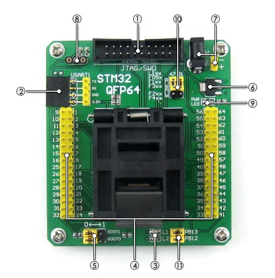
Finally – I just discovered test boards with sockets for STM32 LQFP64 and LQFP100. They are a bit pricy – ca 65.- USD yet, but it is a start. These are on the list of things I planned to make because I could not buy them.
Finally – I just discovered test boards with sockets for STM32 LQFP64 and LQFP100. They are a bit pricy – ca 65.- USD yet, but it is a start. These are on the list of things I planned to make because I could not buy them.
I currently plan using INA194 that have a 50x gain. As our max voltage in is 3.3V this means the max voltage over the shunt need to be 3.3/50= 66mV. Given a max current of 2.5A that gives a Shunt resistor R = V/A = 0.066/2.5 = 0,0264 R or 25mOhm.
Now – 2.5A over 25mOhm is 0,156W which is fine since the 1206 resistor is 250mW.
If I use 50mA that gives 0,00125V (1,25mV) into INA194. And with a gain of 50x that is 62,5mV into the MCU. This is where we get into trouble because INA194 starts being inaccurate below 50mV in. I am not at all sure I actually can measure these low currents, but I do have one SW trick to help me.
We are NOT measuring a constant current, we are measuring a PWM pulse current, and the current we will see is 2.5A for 1mS and 0A for 999mS (just an example) due to the nature of the PWM. In software that becomes 2,5A / 1000 = 0,0025mA in average over a sec. So, if I take advantage of the 2,5Msps capability on the STM32 M4 I should be more than ok. I just need to make sure my sample frequency is at least 2 x the PWM frequency, but the higher sample frequency the better in this case.
Yet another trick is that I know then the Pulse is On/Off, and since we have raw data (no electronic filtering) I can eliminate noise then the pulse is off – as I simply know there should not be anything there. This is more difficult to do than I write here, but I will dig into it.
I used 2.5A as an example, but pulse current is V/R and can be higher that the rated max. This is why some MOSFET’s are rated to 160A with a pulse current to 400A etc. If we have motors with low inductive R we reduce PWM duty to maintain 2.5A in average, so I might actually need to cut down even further on the Shunt to avoid clipping on pulse currents, but I will not worry about that for now. I want to experiment with actual values because you can only cover so much in theory. Noise etc also add to the picture and is not easy to predict or model accurately.
The irony is that I removed passive filter components because of lack of space, and those filters would have prevented us to see the pulse currents. Now – since I have raw noise in I can actually use SW and see far more accurately than I would have done with analogue electronics. This is an excellent example where you need a good interaction between a HW and SW engineer.
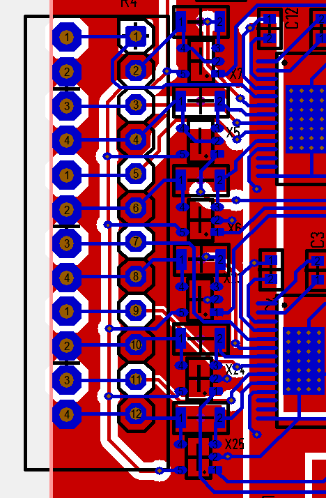
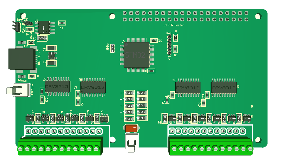
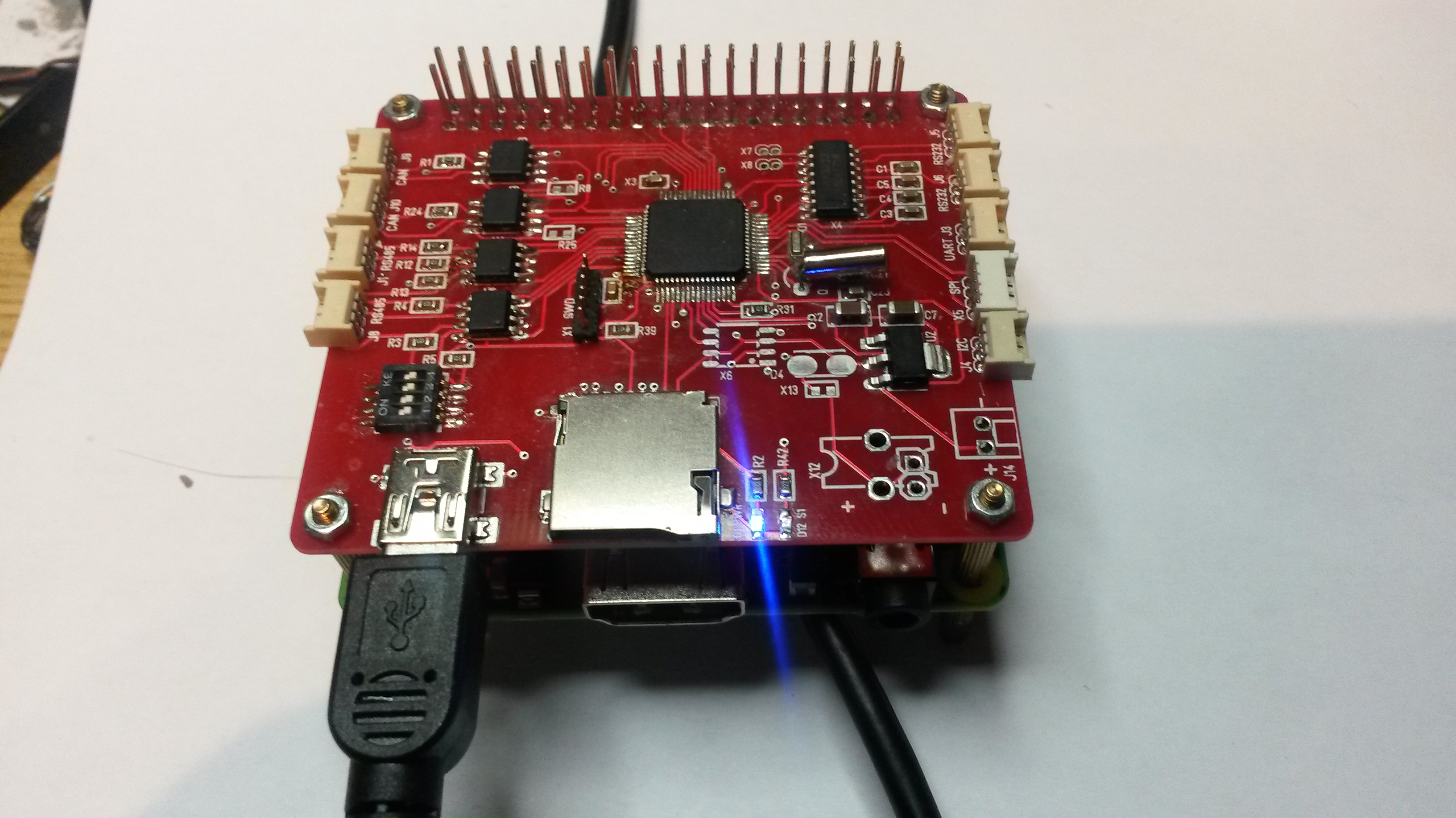
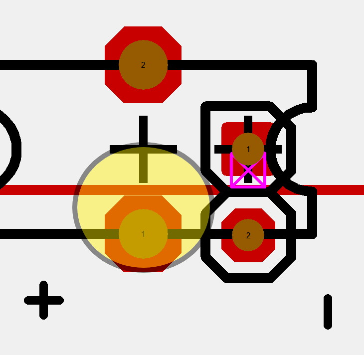
Left side of the 3-Phase/Stepper/PWM Hat done. This is the hardest bit, but it went much easier this time because the previous attempts gave some hints and lessons learned. I am far from finished, but it is not hopeless. My main concern is the ground-plane getting to fragmented and unable to support the currents – but, I am not out of tricks yet.
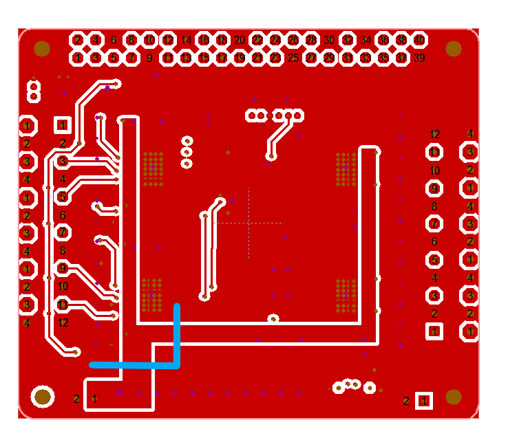
This picture show the back-side and the ground input is actually the “2” in the left, bottom corner while DRV8313 are on the inside of that thick 36V power lane. While Ground is connected you can see that it is thin on some places due to the density on the left side. it will be equally dense on the right side, so what I am considering is to add a bridge on top lane (illustrated in light blue) to ensure that I have a direct path that will support the currents I need.
I must admit that doing PCB routing is a bit like a puzle. You need to like these mind games if your going to be good at this. I know many electronic engineers who seldom do PCB routing – only schematics.
I have suffered “Crash O’ Mighty” on this Board a lot. I use a free version of a Target 3001 EDA based on Java and well – it does crash a lot. I am also more and more feeling the pain and limitation of 2-layer designs, but I will need some time to get started with KiKad.
What worries me a little is the signal integrity of the current sensor signals. But, it is nothing I can do about that. The issue is that the ADC signals need to pass strong PWM signals, so that current on one PWM might give a false signature on a 2nd PWM’s current sensor. I do however have the option to filter and compensate for this in software, so lets see. I do expect noise on these signals regardless.
I am returning to this board to make a new attempt because it is a very attractive board to make + I just received another bunch of DR8313 chips and Connectors that I need to use for something. What stalled me on the last attempt was several issues:
The 2.5A limit is worst for PWM stand-alone signals, but the actual target is 1A and I can always combine output’s to achieve 2A. I need a bit of testing, but I think that will work just fine. 2.5A is just fine for 3-Phase and Steppers. The one drawback with steppers are that we need to do a bit more logic in code, but we have the MCU capable to do that and I want a stepper with current sensors.
The one thing I need to test is the current sensor. INA194 have a very attractive footprint and voltage range, but I am a bit concerned about it’s datasheet. It basically need 50mV input before it become ca 1% accurate and with a gain of 50x we basically run out of 3V range at 60mV input. I also use 0.25W shunts to get 1206 footprint (size) so it’s not straight forward to decrease gain and increase shunt resistance as I start using to much effect.
I also need to test currents through DRV8313 and I have a small 3-phase that I can use for that purpose. This is a simple test to run constant current and use a finger to test temperature to see what I can get away with without a heat-sink. But, heat-sink is actually straight forward because DRV8313 use a pad connecting to ground so we went out on the back-side and can add a heat-sink directly to the PCB.
What I will do is to mount INA194 on the breakout boards I made earlier and test. The reality is that I don’t need current sensors to be that accurate, but I need them to indicate levels on low currents (50mA and up). Used on a 3-phase that helps me detect rotor position so I can use vector based algorithm’s. And for a stepper it indicate torque so I can detect end-stops without an external end-stop sensor on CNC machinery.
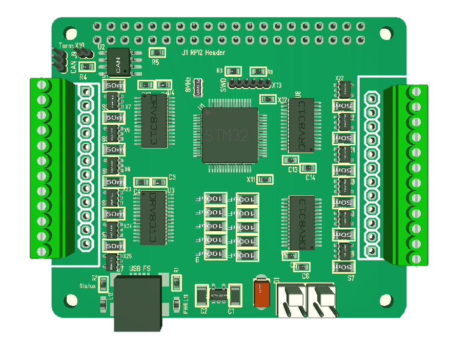
I can easily make a separate 3-phase, stepper and PWM board, but the combined functionality of this board makes it very attractive to implement it. I can always go into 10cm width to get more space, but I want to make one more attempt on the current size format first.
The different approach I want to try is to move the connectors to the left and right and have USB/Power in the middle. I believe that will allow me to get away with less space around the MCU + I get 2 x DRV8314 on each side.
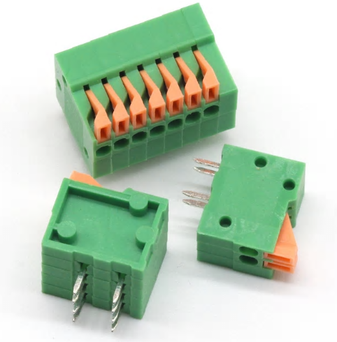
As for space – the connector account for a lot here and I could get away with a lot less if I made a specialized 3-phase or Stepper Hat as I then would use right angle Micro JST connectors. It is the need for a combined connector that made it attractive to use this footprint. But, I also notice that the smaller JST Connectors handle less mechanical stress. The connectors I use here have 2 pins per channel to handle to make them more robust.
The 10cm wider board will need different width of these connectors, but as I get more space I could also consider adding galvanic isolation between Driver and MCU. We are after all dealing with a lot of effect and coils here and I will need about 6mm to support an array of photo couplers. A quick look at the mockup below indicate that this actually might be possible.
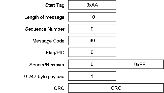
Message Header
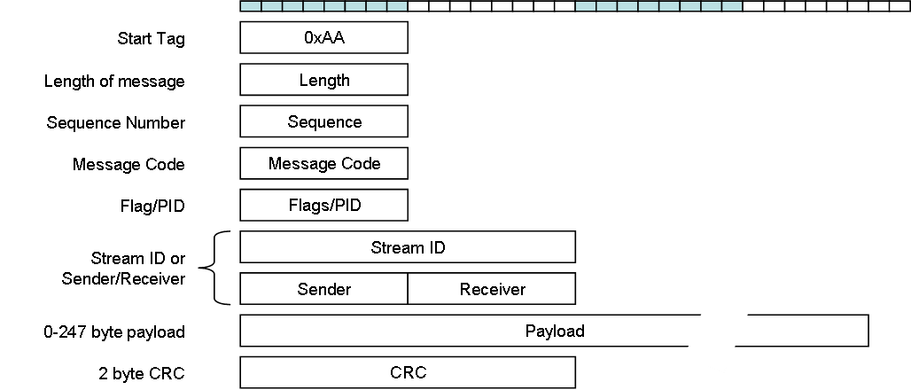
This is the new message format that I will use on SPI, RS485 and Ethernet. For CAN I am not sure yet. I might want to take more advantage of the strong capabilities in CAN, but lets see.
The format above allows me to communicate device to device in a network, but at the same time also allow for streams of information that is not device depending. A device number is local for the network, meaning that all 1:1 messages on the link etc uses this format. Right now I want to establish a RS485 protocol that can support CLI as well as more advanced schemes. Next I want to bring up SPI and later CAN. But, I also want to add Modbus and CANopen support later – loads of fun.
Using a per Message CRC on Ethernet is not needed, but it allows me to maintain end to end Message integrity.
RS485 is in this case running 2Mbps, so I want top-side to send a Start TDM signal with a list of devices that will respond. Device 0, Device1 etc. The logic is simple – Device 0 is always Network Master starting the loop by sending a list of devices that need to respond. At the end of it’s own sequence it sends EOT and device 1 starts within 4 ms etc.
I have 3 XPortHub devices I can add into the network for testing so we can get this off the ground.
TDM Sequence
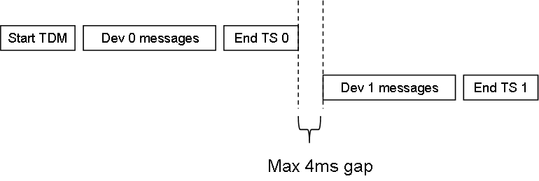
This illustrate the TDM scheme between 2 nodes in a Network. Start TDM is only sent from device=0.
Start TDM
The content of Start TDM is a list of devices that will respond and in what order. Each device have a time-slot of 4ms to respond before the next takes over. Devices not on the list will be silent.
End of TS
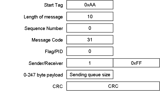
End of TS (Time-Slot) is the last message send by all devices. This is broadcast and gives the next device a 4ms window to start sending it’s Messages. This scheme is used on RS485 and SPI. RS232 and Ethernet are full duplex and I want to evaluate options for CAN a bit later.
Baudrates like 110, 300, 600, 1200, 2400, 4800, 9600, 14400, 19200, 38400, 57600, 115200, 230400, 460800, 921600 are rather standard, but what do you use to set 10Mbps?
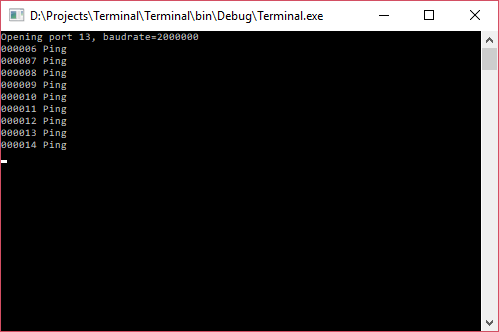
Testing with a Windows PC I manage to get 2Mbps as shown here, but Windows is not able to open higher frequencies. I am in this case using USART6 on STM32F405 capable of 10Mbps speed, so it’s Windows that is the limitation.
I have not tested everything yet, but rev 1.1 of XPortHub need a few changes:
These are just minor adjustments as the board seems to work fine!
This was a rare bug on the XPortHub! I have not bothered to test the super-cap/battery for the VBAT much, but suddenly realized as I was doing other changes that I had an error message related to this. And correct – measuring the PCB I have a self infected short-cut. CNC machinery making PCB’s require a minimum of 0.14mm distance between lanes to guarantee that lanes are not shorted and this is shorted by accident.
The EDA warns me, so this is me overlooking the error message. I have a package overlap here because I have an alternative connector – this generate error messages I have to overlook and I obviously overlooked one I should not have overlooked. It’s no big deal because this could very well have been connected. The only component I shortcut is a diode that should prevent leakage back to other circuitry. But, it means the battery will power the entire circuit, not just VBAT.
I keep repeating myself – I always need a minimum of 2 PCB layout’s. The more I push to work faster the more of these minor bugs I am guaranteed – but, that is ok – I just plan for it.In this case I want to add a proper battery holder on 1.1 anyway.
FATFS is a middleware component you can add to create a MicroSD API with full file I/O support. It only takes a few clicks with CubeMX and you have an API with the following and more:
I finally managed to sort out the CubeMX/SW4STM32 error so I can move on a bit. The XPortHub (pictured above) is coming together very well. Sadly I have to upgrade this due to the Flash footprint error, so I will make some other adjustments as well.
CubeMX auto-generate all drivers with pin-setting, FreeRTOS, USB driver and even the FATFS system allowing the Micro SD Card to be used as a disk.
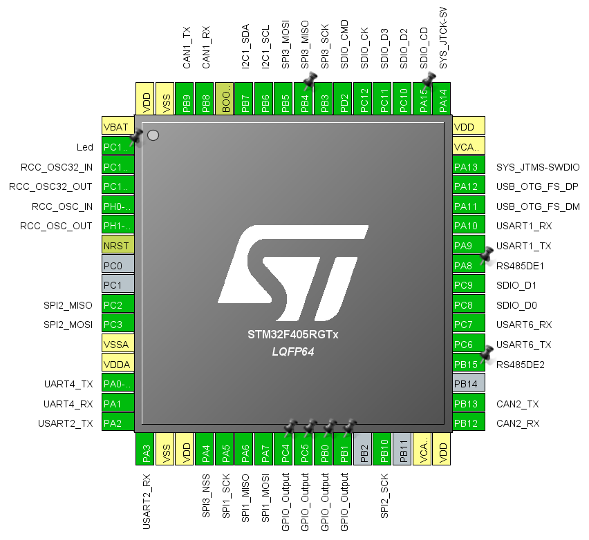
The pin-out above shows how dense this design is getting with only 5 spare pins. Using the USB as a serial link with a little console app this basically have more content than my first IBM PC back in 1983. It bring back some nostalgic reflections to my early days fiddling with DOS and C compilers.
What I will do next is actually to create a terminal application and a CLI with a Utility package that in many ways with mimic the old DOS/Console days.