HMI Solution

I want to work on creating a modular HMI solution. I already have Raspberry PI with HDMI, Keyboard and Mouse interface, but I need a solution for smaller displays, specialized button’s and knobs to go on instrument type projects. The concept I like is that an embedded device can store it’s own interface and then send that to a HMI unit that operate the display part as an intelligent IO. This means that the HMI itself behave more like an HMI Browser drawing graphics according to a spec while the embedded device receive events like “Button OK Pushed” dealing with the actual user input.

Several solutions that uses this scheme exist, so this is not a new invention. But, I want to put it into a system where I can add HMI components on modular bases.

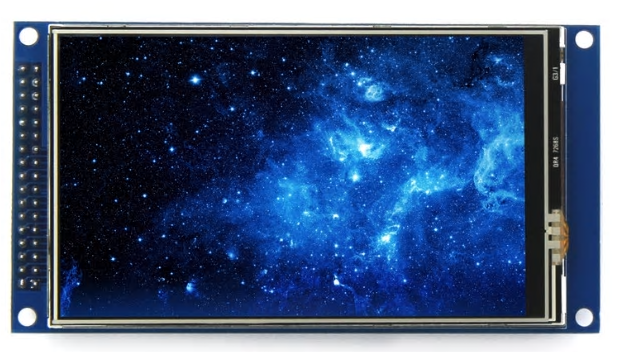
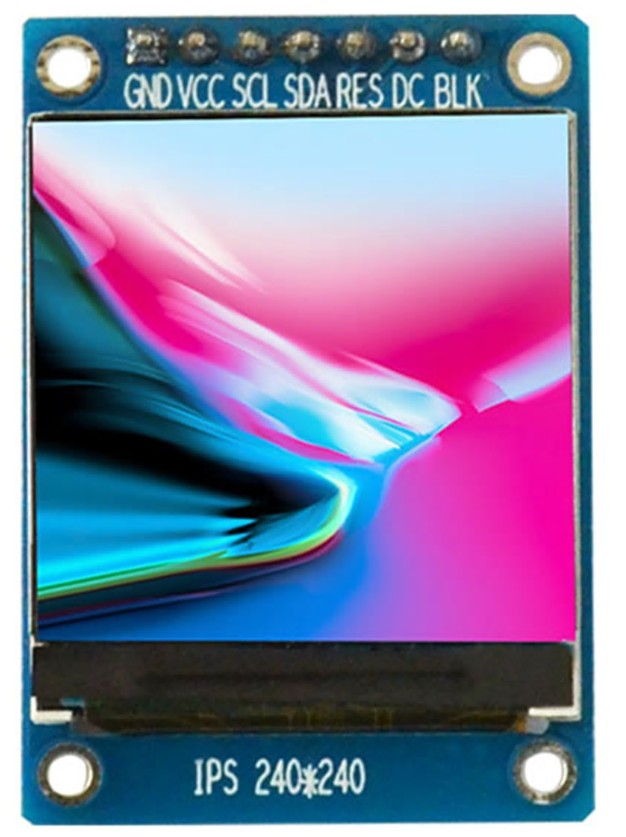
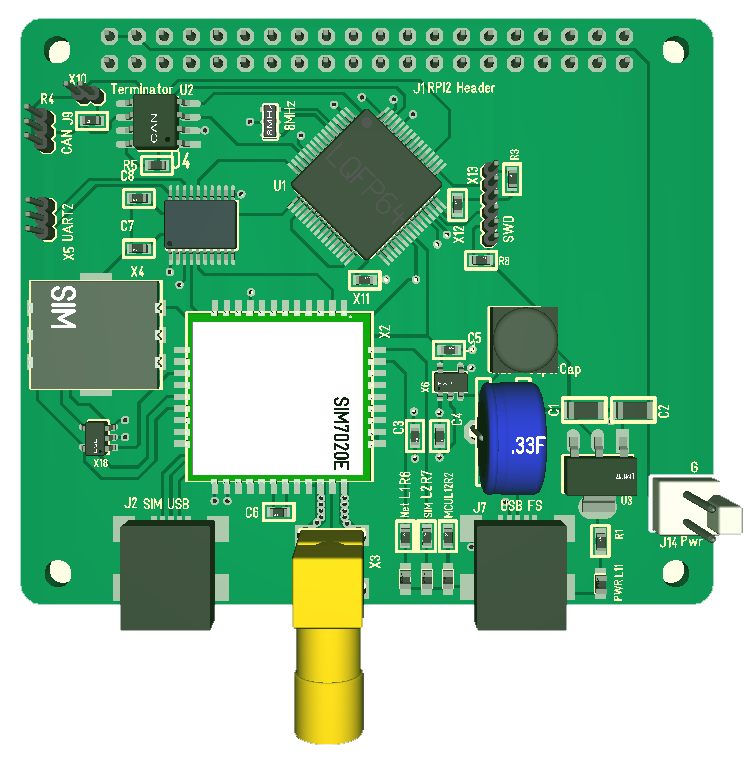
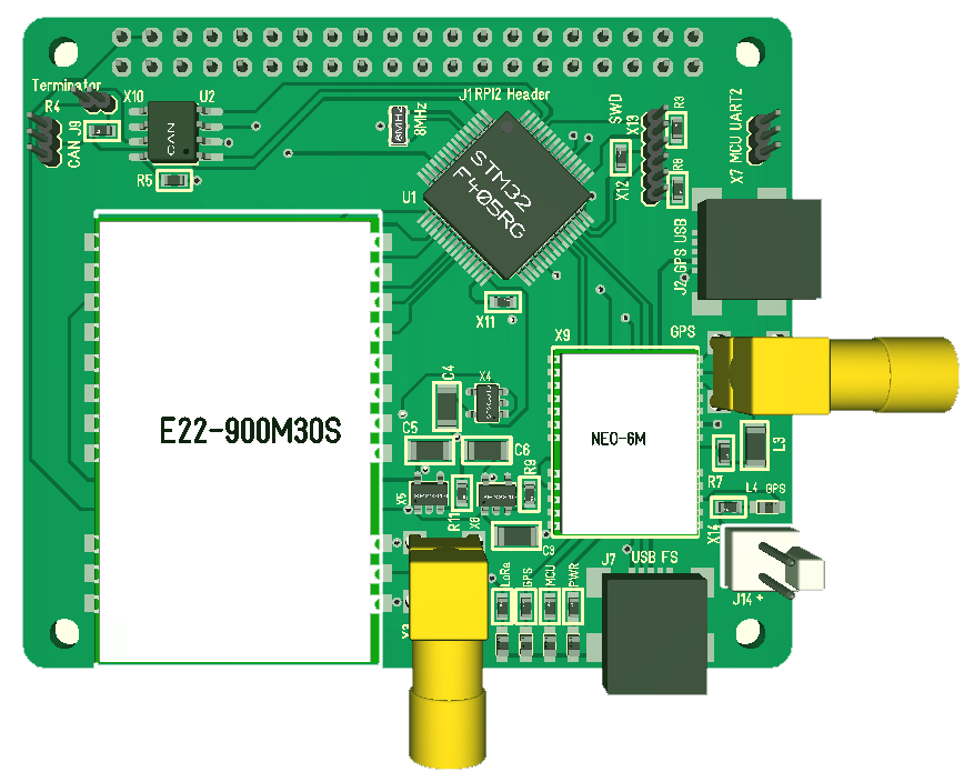
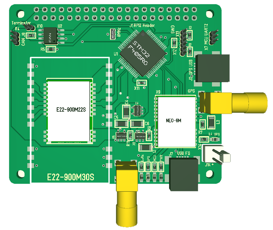
The 2 displays above are my first targets. The larger 4″ display have 800×480 pixel resolution and a 2×17 pin connector using OTM8009A as driver. The interface is either SPI or parallell and it exist sample code for STM32 on this. The smaller display is 1.3″ and 240×240 pixels using SPI interface. These 2 displays caught my attention because of their design with screw holes, bare-bone adapter, high resolution and low cost. Each driver will require a lot of code + I need specialized cables so I will select a range of displays I like and stick to them.

The next part of the project is buttons and knobs. Basically a system to build a customized HMI using modular components. My first thought here is to use the smaller STM32F030F4 or F042F6 on Half Duplex SPI or RS485. I could create a back-plane with PCB screw holes in array formation allowing smaller modules to be added and cabled up. One module can be the display while the rest is knobs and arrays around it as needed. I have to work on the mechanical solution here to avoid that screw holes occupy to much space making this impractical to use.

The big win by doing this is that customized HMI solutions basically is to expensive for low volume products/projects “as is”. So, by making a modular system we should be able to assemble our own customized HMI based on components that are low cost due to volumes even if our project is an one off.

So, to sum this up I am actually talking about several PCB’s:

  • A Hat with cables/interface to displays. I will try to make it possible to mount displays directly, but I don’t thing it will be very practical – so I assume a cable between the Hat and display as a minimum and then a network attaching add-on HMI modules.
  • Rotary knob module.
  • Button arrays
  • Led’s.
  • A backpane plane to plug Things into.

LoRa+GPS Hat

This is one of my more exiting projects as I add a LoRa transmitter and GPS to a Hat. E22-900M30S support 12km range while the smaller E22900M22S support ca 6km Range. I have received units and PCB so just waiting for a time-slot to work on this Hat.

  • Raspberry PI Hat format
  • 42Mbps SPI backbone bus
  • CAN Bus
  • LoRa 868 or 433 Mhz
  • GPS
  • USB
  • TTL UART

CAN Adapter

Many of my newer devices have CAN so I wanted a simple USB(CAN adapter. It is nothing special with this project. I used a STM32F105 with USB on one side and CAN on the other. A minimalistic UDB-CAN Adapter just6 to avoid the need to pay a fortune for these.

The first rev 1.0 missed an external x-tal that turned out to be a mistake as USB required this. Once this was added on rev 1.1 the adapter worked.

It should be noted that XPortHub have both USB, 2 x CAN, 2xRS485, 2xRS232 and more so it’s questionable if I continue this Project.


60V 50A 3-Phase Driver

This is a specialized 3-phase driver that uses DRV8301. It is more narrow than the 4 channel design and not so complicated to build. I did this design before I did the larger 4 channel design so it is several things on this design I improved on the 4 channel design.

  • Temperature sensors are still external on this one.
  • No smart way of adding capacitors on Power In.

The intention with the 3mm air wires on the back was to have heat-sink on the top. I later realized that I will be better off using a heat-sink on the PCB on the back, but that is an assembly change. I can also shorten this by 1cm by removing the air wires at right and take the output directly from between the MOSFET’s.

The total size of this is 25mm x 100mm and I have a heat-sink for this, so it’s an awesome design. It will sustain ca 50A, but can go higher for a short moment. This design is also very close to the Vedder ESC design so we can borrow that source code with minor modifications.

The one change I am considering is the temperature sensor(s). I seriously would like them on the PCB, so lets see. I have not ordered PCB for this yet because I am considering a few changes + I want to build the 4-channel design first.

Comparing this with the more universal 4 channel I must admit that this has one advantage – size.

60V 50A Motor Driver

This is an awesome design allowing 60V @50A on 4 separate Half H-bridges. The design is a step up from the 30V/20A design using more powerfully MOSFET’s and adding wiring to support higher currents. It is also a Hat design, meaning I can add Hat’s to extend the controller. The pic above show my specialized motor controller PCB’s with this one at right.

I face some practical challenges testing this. Some of you might recall that I had challenges with 20A – I simply had no PSU that could support it. Or well – I actually do now. I do have a 60V/20 PSU and plan to build 2 of these.

My main concern and maybe biggest mistake is however the design of the air wires. I have 2mm wires, but lack the 3mm and realize that the way I have designed the 3mm makes them very difficult to create and solder on. This is a design with components on a single side intended to make it optional for production, but those wires require a lot of manual work defeating the object.

What I lack on this is a galvanic isolated communication interface. I attempted one earlier, and it worked, but heat dissipation was larger than I wanted. So what I will do is to create a separate Hat for this purpose later.

I should also point out that I might separate this board into 2 boards. One Driver and One controller. The interface between the MCU and MOSFET driver is more or less standard and I could need a galvanic interface here as well which would be easier to add if I separated the boards + it would allow me to add even more powerfully drivers.

The 4 separate channels means I can drive 4 solenoids, 2 DC motors, a 3-phase motor, a stepper motor or any combination. It is 4 x High side current sensors, hall sensors, CAN interface and USB. MCU can be powered by USB to keep it separate.


60V 2A Motor Driver


This is a micro controller using DRV8313 which basically is 3 x Half H-Bridge drivers in a chip supporting 60V and 2-3A out. The design is excellent for a 3-phase driver, DC Motor or solenoids and work perfectly.

The initial version had an issue with the 60V DC/DC that needs to be fixed. DRV8313 have a 10mA PSU, but this is not sufficient to drive the MCU and CAN Interface. The pics are from testing on DC/DC notice the capacitor “Tower” at left. These are the fix for the DC/DC.

Located on this is also Hall Sensor interface and some IO options. I will add a rev 1.1 of this. The MCU is either STM32F103 or STMF303. The picture show early testing of the DC/DC only. This is a bit larger that the DRV10983 base driver, but it is so much more fun to be able to drive the 3-phase from the MCU.

I need to modify DC/DC and I also want to add at least 1 phase current sensor to be able to drive the motor better. DRV8313 have capability for 3 x phase current sensors and STM32F303 have PGA etc. But, looking at that Board I also realize that I am out of Space.

  1. 60V 2A
  2. CAN Interface
  3. STM32F303CB or STM32F103CB/C8
  4. DRV8313
  5. Hall Sensors
  6. GPIO pins

28V/2A 3-Phase Driver

This is the smallest of my dedicated 3-phase controllers using DRV10983 and STM32F030F4. The entire controller is the size of a fingertip and will run a 3-phase motor using sinusoidal algorithm. The controller works, but I was not impressed over it so far because it tend to loose control over the motor I use for testing and start drawing to much current until it stops on over-current.

It is an excellent design controlling a motor 28V/2A from a very small design. It has 2 interfaces as you can control the motor through pins or I2C. The design needs to be optimized, but it’s nothing wrong with it so I want to see if I can get more control of the motor. If not it is not worth continuing using DRV10983.

30V 20A Motor Controller

This is my old universal motor controller that actually worked quite well. The main challenge I had was dodgy MOSFET’s. As I moved on I also moved to 60V and 50A + a Hat design that is a bit larger, but I have been thinking about updating this smaller design as well.

Todo on rev 1.2:

  • Max 30V, meaning 24V
  • Max 20A. I think 15A is more realistic, but the MOSFET’s can handle very large puse currents.
  • 4 separate Half H-Bridges as before
  • 4 BEMF sensors
  • 4 Current sensors. Revision 1.0 uses INA210, but I want to swap that for INA193/INA194.
  • Simplify some filters because we can do them in SW.
  • Replace PSU with 7812.
  • Replace LM1117 with SPC3819
  • Add connectors for caps on top.
  • Add 2 temperature sensors between MOSFET’s.
  • Replace connectors with JST Micro.
  • Add space between Shunt and connectors.
  • Remove 6 screw holes.
  • RS485 as before, but see if I can add CAN and TTL UART.
  • Export more spare IO.