3KW 3-Phase Outrunner


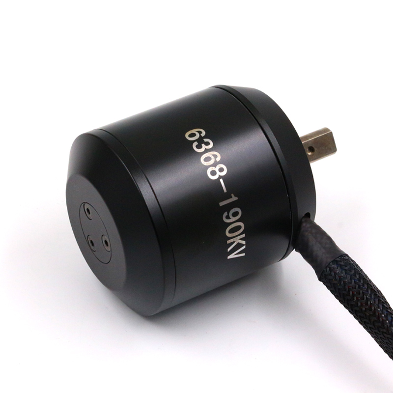
This pic is of a 6368-190KV while I just received a 6368-280KV – a 3KW Outrunner BLDC w/Hall Sensors that costed me 60.- USD all in all. This will be my 3-phase test motor on the 3KW Motor controllers thought while my controller is max 60V @ 50A these motors have a spec 36V @ 90A max. I will use it at 48V and max 30A. I am not able to test higher currents due to 2 reasons (1) rev 1.0 of the controller have a PCB error on heat dissipation, and (2) I will struggle with more than 30A from my Lab PSU’s – or well – maybe I can borrow equipment for testing later or switch to batteries on a real project.

This motor is very cool. 3KW is a very decent scooter and it has some weight to it. The challenge is however that it is an “outrunner”, meaning it rotate the motor housing. I need to fix the motor to a plate to be able to test it, but I will find a solution. The motor also have a nice hall sensor cable and some nice 3-phase connectors. 


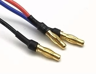
I need to see if I can find the female version of those connectors because I really like that solution. The thickness of the cable is less than I expected for something rated to 90A, but lets see what happens as we start spinning it.

I still do not have a heavier stepper motor to test with yet. I have looked, but they cost to much so I will do without for now.

As for actual projects I am considering buying batteries and making my own electric bike/Scooter. 3KW is far to powerfully for a bike, but we can use it at 250-500W. 250W is restrictions for electric bikes in Norway. If I buy a registered Scooter and rebuild it to be electric it would be ok with 3KW. I probably can buy one cheaper than it will cost me to build one, but where is the fun in that?

Programmable DDS – Part 2


This illustrate the main functionality I want to achieve. The DDS can generate waveforms as well as more classic squares, triangles, sinus etc. I would like a signal that can be amplified to +/-20V and given a base offset anywhere within that range.

The blue line illustrate a more classic square signal starting at 0V, while the red line illustrate a programmed signal with any values between +/-20V.

I think +/-20V is a nice objective and I will settle for 100mA out. AD8008 offer me a max 12V signal, so if I use that I will have to settle for a 12V delta positioned between +/- PSU boundaries.

In fact – LM317/LM337 have +/-36V as a range, so I should be able to achieve a compromise if I can amplify the signal from the DDS to 12V Delta and adjust the base offset to -30 to +30 or something. I think this offset adjustment is straight forward, it is just that I have not done it before. I realize that I am a bit inconsistent as I draw +/-20V and talk about +/-10 to +/-30V. I will go for +/-30V if I can, but I will settle for +/-10V if I must. I will also go for 1A out if I can, but I will settle for 100mA out.

Selecting a DDS chip is something I will return to. I indicated AD9851, but it is a long range of chips with frequencies up to 1Ghz and various functions. Their pricing range from 5.- USD to 50.- USD, but these are key to generating functionality at decent frequencies.

Selecting amplifier is the same. AD8008 is a candidate, but I would like a chip with a larger voltage out and preferable digital gain and offset. The more I can get packed into chips the more realistic to get this all on one Hat.

Having this on one Hat is an objective, but I will settle with DDS on one and Amplifier on a second if I have to. In fact – I wonder if I could benefit from 3 Hat’s – One DDS with 3V out, One more capable low frequency amplifier and one high frequency amplifier. Having these as Hat’s have values of their own + the Hat system means I easily can add as many channels as I want on the actual function generator.

It is a lot of loose ends, so it will be some time before I can settle a design that I am happy with. I am also a bit on on the edge of my own skillset here so I have asked someone who consider this “babyfood” to assist me as we move forward.

One main concern is PCB layout. I think this needs to be my first project using 4 layer PCB.

Programmable Function Generator – Part 1

I think I can achieve a decent function generator by combining AD9851, AD8008 and AD5231 as shown above. AD8008 is an amplifier with 650Mhz bandwidth and it uses a resistor for Gain adjustment – I think I can use AD5231 for that purpose. The Voltage input is max 12V so I should in theory be able to deliver 100mA on a programmable signal from 0 to 12V out.

I seriously would like +/- 10V (or even +/- 20V), but the last amplifier stage is difficult to achieve with both frequencies and space intact.

I earlier mentioned using a programmable resistor to control an analogue PSU input and this is still an option. Assuming the 12V in is isolated I could use LM317 and LM337 with a dual potentiometer to programmatically set ground out. I basically trick AD8008 to believe it has 12V DC, while I adjust ground out to be anything between 0-12V giving a signal that can be 12V size between +/-12V. I think this is possible, but I need to experiment a bit on what I do here.

Size and frequencies are a main concern, so it is possible that I maybe should split this into 2 Hat’s – one with AD9851 and one with AD8008 and the PSU part. Frequencies are – well – 50-70 Mhz out will be nice, but I am happy with 10Mhz as a start. The issue is that once you start dealing with 50ich Mhz and higher you also start to get into high frequency concerns on the PCB.

This actually starts looking possible – I think I want to start with the PSU part – simply use 2 x AD5231 and see if I can achieve a programmable +/- 12 V out the way I hope. The next step is to verify that I can use a AD5231 to adjust gain on AD8008.


Terminal Code

The code snip below is the C# terminal code I just knocked out. As simple serial terminal as you can get:

namespace Terminal
{
    class Program
    {
        static void Main(string[] args)
        {
            string portName = "COM15";
            while (true)
            {
                try
                {
                    SerialPort port = new SerialPort(portName, 2000000, Parity.None, 8, StopBits.One);
                    port.Open();
                    Console.WriteLine("Opening port " + portName + " baudrate=2000000");
                    int x = 0;
                    int c = 0;
                    while (true)
                    {
                        if (port.BytesToRead > 0)
                        {
                            String s = port.ReadExisting();
                            if (s.Length > 0)
                            {
                                Console.Write(s);
                            }
                        }
                        else
                            System.Threading.Thread.Sleep(20);
                    }
                }
                catch (Exception e)
                {
                    System.Threading.Thread.Sleep(20);
                }
            }
        }
    }
}

easyIPC Dev Setup 1

My next task is to get SPI working on the backbone of my modular control system, so I have assembled 2 x XPortHub’s both connected to a separate ST-Link. One the Hub’s have a RS485 used as debug port, but I intend to bring up USB ports on these later.

The picture above show both XPortHub’s connected. The 5V from the USB feeds both Hat’s that both are connected to each their ST-Links. What was holding me up was the 2nd USB cable, but I bought 10 extra now.

XPortHub is excellent to use for infrastructure development due to it’s high density of communication ports. With separate SD cards and UART display port they basically are small PC’s.

Multiple ST-Links

SW4STM32 allows you to maintain multiple projects and have multiple ST-Links active at once. This is a welcome feature as I now need to program several at once to get backbone SPI working. I finally got the 10x USB cables, so everything is set up and working.

This also means that I start using SW4STM32 on regular basis as I start digging deeper into the SW components on my Hat Project.

Home made Z80 Computer

I have seen quite a few attempts on making vintage computers, but this “Homebrew Z80 Computer Kit” costing 199.- USD is very cool. This is actually a very cool design. If this had popped up at this price some 40 years ago I would have bought one.

I do however love the modular design concept that is used here. It brings back many good memories from my early days in this science. I am interested to know how many sales these do. It’s not going to be that huge, but still – it is plenty of Z80 enthusiasts out there. Well done! The link is below.

https://www.tindie.com/products/Semachthemonkey/rc2014-pro-homebrew-z80-computer-kit/?utm_source=hackaday&utm_medium=link&utm_campaign=fromstore


Google Web Designer

I have searched for Web Designers a few times and recently found Google Web Designer. This is a full HTML5 designer with  WYSIWYG designer as well as Code Editor. This looks like it could be the answer to my web design needs should I decide to use my own time to dig into this.

Google follow a known Developer scheme where you drag components into the screen and set properties. After that you can manipulate the content with HTML5 which is a mix of HTML, JavaScript and CSS. Google Web Designer is very convincing as it assist a lot in doing the more fancy 3D stuff. It is not straight forward to use, but I can see that this would be worth learning should I decide to pick this up.

What I really would have liked is database aware components. The content you see in this blog is stored in a SQL database, and to create a blog I need to execute a few SQL statements. Delphi/C#/VB all did this through components that made it very easy to get going. But, you can add user components to this, so lets see. I am not sure I actually want to use this or take over editing my sites, but it’s fun to experiment a bit regardless.

Reading this blog

I basically keep my notes here in this blog, so to follow a project you just click on the project in the left (obs right) bar as that will filter out entries. This is so far the only real change to this blog as I keep searching for alternative themes.

I actually found one WordPress theme that was better than this, but one of the challenges I face is that they leave to few options open for user control, so I fail to customize the themes into something I like reading. What you read here is a compromise – it Works and it only costed me a few hours of my own time. I would like to avoid spending weeks programming a WordPress theme or my own blog system, but I am starting to wonder if I need to.

As for WordPress – the system itself is free, developed in PHP from what I can tell. Most of the themes are however commercial. TBH you can easily pick up database skills and spend a few weeks to get your own customized web-site. The blog you see in front of you is a retarded compromize compared with some of the stuff you find out there. It is not difficult at all if you have the interest and time.

WordPress is great for someone without time or programming skills to get a blog running. It gives you a base site with a few clicks and the system itself is great. But, it fails greatly on customization options. One example is the post header in this theme – I can’t change the font parameters, so I changed theme and now I can’t Control the right bar etc. 

But, this is what you get then you use someone elses product – you accept their limitations,  quality – or lack of such – and schemes to earn Money. WordPress earn their Money in the customization of themes.

Protocol Analyzer – Part 1

The protocols I use on CAN, serial, Ethernet, Wifi are all part of a easyIPC package designed to co-exist in a complex network. This is at the core of the systems and I need a tool that can visualize the messages that pass on various levels. This tool is called a “Protocol Analyzer” and without this you will waste hours trying to figure out what happens.

I use the name “Protocol Analyzer” or just “Analyzer” for this project. It actually consist of several projects that add up to a package of hardware and software. The concept is simple – I will use my existing adapters or Hat’s to collect data from – basically sit in 3-state and copy messages up to the PC where I can present them and analyze their content and sequence/timing etc.

My QT based framework is excellent for this. I basically just need to add a fast, virtual grid component and create some kind of database on log files. It’s a bit of work, but I have experience from doing this in the past and have been using analyzers for years in telecom so I know what I want and why I want it. I have listed some basic objectives below:

Req Description
1 Be able to display messages real-time with max 250ms delay from capture until visualization on screen.
2 Be able to synchronize time stamps and adjust time differences if needed.
3 Be able to use disk as endless storage so we can leave the log part of the analyzer on and revisit message sequences afterwards.
4 Intelligent filtering of what is displayed so we can focus on what we look for.
5 Capable of recognizing proprietary messages that we add through XML spec.
6 Capable of testing rules like message sequences and content checks and visualize errors automatically.
7 Log raw Message content only. The rest should be a presentation issue based on XML settings.

I will add more to this list later. You will start seeing screenshots of this project soon.