New SWD Adapter


First draft of a new SWD adapter designed to be installed/removed while the Hat is inside the stack. SWD on this will work even if you miss a row while connecting because Reset is pushed to 3.3V and all other signals are duplicated on both rows.I will make another using ST-Link V2 connector directly. Currently I use 10cm wires between the USB adapter and this adapter card. Could be interesting to mount it directly, thought I am not convinced that will work well while the Hat is in a stack. Let’s see.

Sensor Hat – Mockup 3

Just added the package for CR1220. The actual package look at bit different, but this has the correct footprint and size. This looks like a large component, but it is not – it is more an indication of how small and dense these Hat’s are. I will attempt to update the next revision of XPortHub with this as well.

CR1220 is a small battery that in this case support RTC VBAT. I The battery have some size on the PCB, but it is all empty space underneath so PCB routing in that area should be easy – I also added the external power connector back. What I will do a bit later is to print a PCB copy on paper and add the actual connectors as an exercise to verify that it’s not to dense. I can move those 2 led’s into the card etc. I could also move leds in between USB and Power connector to avoid that they get to close.

The picture above show the green lines that needs to be routed. This looks straight forward – not to many dense ratnests. I probably need to turn J16, J17 and J16 around to minimize crossed signals – but, lets see. I am still on only 2 layers so I prefer to route as much as possible on top layer and use the bottom as ground plane.

Another concern is the 6 pin SWD connector I use here. I used a 2×5 pin earlier and wanted to simplify that since some of the pins was never used. But, a 2×5 pin is easy to get female and male headers for. The only solution I have for 6 – pin is to either use a 2×5 pin adapter or add a JST Micro connector. The intention was to use the JST Micro connector, but it was unpractical to connect/disconnect + it added 10cm wiring on SWD that made it challenging getting the SWD signals working. I have to think about this, but I am considering moving back to the 2×5 pin header and specialized adapters similar to the one below.

This is an SWD adapter I drafted a long time ago and never ordered. The adapter Connect between the 1.27 Pitch on the PCB and a 2.54 Pitch header that makes it easy to connect ST-Link. It show the male header, but I could modify this to connect directly to the small ST-Link SWD adapter and it should be straight forward to connect this even if a Hat is in the middle of a stack. The original design added 5V and a RX/TX, but I want to simplify this for GND, 2 SWD signals + Boot + Reset + 3.3V. I actually only need 3 pins for a SWD alone, but I need 3 extra pins to support Boot and Reset through the adapter. I have never needed Reset, but I have used Boot a few times.

Sensor Hat – Mockup 2

I have still not routed this, but schematics and component location is getting in place. I have to make a package for CR1220 battery holder for RTC + I would like to make the proper packages for the connectors as well. I dropped the extra CAN and RS485 due to lack of space + I have other cards for those. I also ditched SD card due to lack of pins, but I still have the SPI Flash.

I also have to think a little about what Power I feed out on the ports. I am currently using 3.3V, but I want to add a jumper to select between VIN and 3.3V for the Hat. Ideally I should have done that per port, but that would require 30 jumpers. It is possible I can manage separate for AD, I2C and SPI. Many of the available breakout boards uses 5V due to Arduino, but that said our AD ports do not have 5V tolerance.

STM32 have a lot of 5V tolerant pins, but analogue pins that I use on AD ports are 3.3V. So giving 5V out then you only can receive 3.3V signals might be a conflict. I could add a level shifter, but I actually think I prefer to stay with 3.3V. As always – work in progress.

My backlog of designs I want to do and PCB’s I need to work on is getting huge so I decided to be a bit more systematic and make sure I do proper doc on each design. The “doc” I use is a small document I call “annotated schematics”. It basically take the schematics, block diagrams, 3D models etc and add some notes to them in a paper. If I do a Revision it will add a list of changes to the previous revision etc. This doc only takes a few hours, but it is worth gold a few weeks down the line then things have been forgotten.

The backlog of designs will continue to increase. The main reason for this is because I find it quite relaxing to sit and work with schematics/PCB routing in spare moments. SW is a bit different as it is more complex and require Focus.

Analogue/Digital Input Protection

This little circuit show the passive protection I want to add to each analogue and digital line.

D1 is a TVS diode set to ca 5V, meaning it will suppress spikes above this level or negative spikes. This is the real light-weight protection. The drawbacks with a TVS is that it takes time to activate so we give it a bit of help with C1 + it can only suppress an overvoltage for a very, very short time. It is not a galvanic isolation.

C1 basically act as a low pass filter and need to be calculated correctly to a cut off point. This being a small capacitor will take the spike out of the spike giving the TVS time to switch in. Together they should provide a very decent protection on the MCU, but they do come at a price.

  • Analogue curves might not be linear as we get closer to 3.3V or 5V because the TVS start kicking in. To compensate for this we usually select a TVS that is 5V for 3.3V or similar.
  • Extra components take extra space on the PCB and C1 will also affect input signals a little.

Sensor Hat Mock-Up


An early mockup indicate I can manage 15 connector on a Hat with USB, but I will have to remove the external power connector and one of the connectors are CAN1, meaning the actual number of sensors are 14 connectors. If I dropped I2C and SPI I could just about manage 16 Analogue/Digital sensors, but I think 3 x SPI, 3 x I2C and 8 x Analogue/Digital is more optional. And, as always – if I need more I can add another board. I also think I can add the power connector back by moved led’s into the board. Will be interesting to see what the end result will be here. 

I like these early mock-up’s because they give me a fast reality check. But, it is one more to come – all these channels will require TVS diodes and passive components etc – this Hat will be dense to route, meaning that I might need to sacrifice a few channels on the way – that said – it looks doable. Using the STM32F405 is in this case very good because it gives us juice as we want to drive a lot of sensors and do filtering options in SW later.

And yes – I know I need to make proper 3D packages for those micro JST Connectors.

Generic Sensor Hat

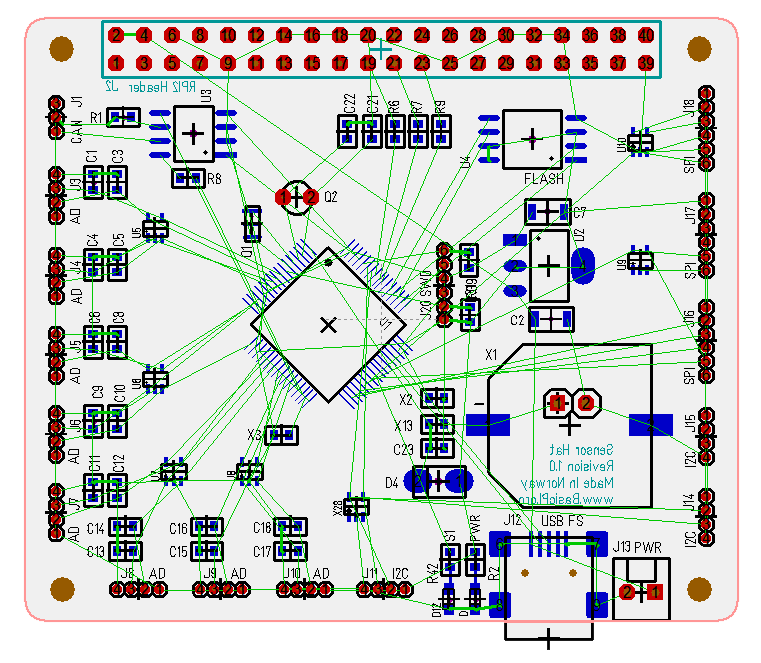
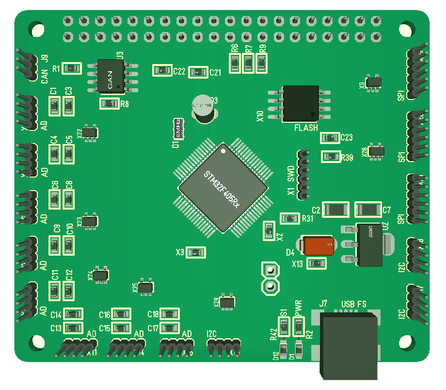
Some sensors like 3D sensors are suited to be mounted directly on a Hat, but a majority of sensors actually need to be mounted remotely to provide proper input. To interface to these I need an adapter card with connectors as illustrated above.

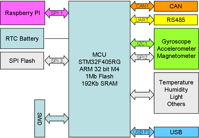
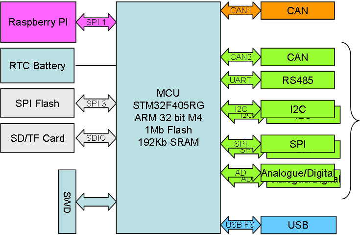
STM32F405 have 16 ADC inputs that also can be used as GPIO sampling at speeds up to 2.5Mhz with a 12 bit resolution. So, what I want to do is to pair an ADC with a pure Digital IO and 3V/5V and ground – a standard 4 wire interface for sensors.

The 2nd interface is I2C. I2C needs 4 wires – V, GND, SCL and SDA.

The 3rd interface is SPI. Combine V,GND, MISO,MOSI,CLK and a separate CS – a total of 6 wires per device as a standard SPI Sensor port.

The 4th is CAN with a classic 4 wire Interface.

The 5th is RS485 with a classic 4 wire Interface.

Most existing breakout boards and sensors can be wired into one of those connectors giving us a very generic sensor hat. Just a few case studies:

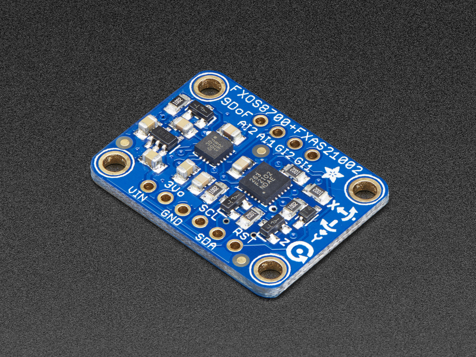
My last post was about a 3D Motion Sensor also known as a 9-DOF. It is 9 sensors available through either I2C, SPI or both.

Ultrasonic Wave Sensor is well known. They cost < 1USD and can detect movement/distance in ca 5 meters range. They send a 40Khz ultrasound pulse and detect the time to the feedback. These sensors have a pulse output, meaning you need a digital IO pin as interface. They also needs to be mounted remotely as they need to be positioned where on the edge of vehicles. They interface well to the 4 wire analogue ports.

Capacitance Soil Moisture Sensor is a long stick inserted into the soil that give an analogue value out describing how wet the soil is. Some of these sensors use a digital threshold chip so the actual output is digital 1. You basically need +3.3V, GND and an ADC signal for these. so it’s a good match for the 4 wire analogue port.

DMT22 is a temperature and humidity sensor. It basically report the readings using a proprietary digital, single wire protocol. You use a GPIO to read pulses that convert into a binary string etc. It is a good match for the 4 wire analogue port.

DS18B20 is a well know temperature sensors using it’s own single wire protocol. This sensor is low cost and you get it in 1m cable length well suited for outdoor usage. It is an excellent sensor to measure temperature at various points. DS18B20 is also available in TO92 package. Again an excellent match for the 4 wire analogue port.

KY-037 is a breakout board with a small microphone. It gives an analogue sound output as well as a digital sound indicator output. It cost < 0.5USD. It uses a 4 wire interface that is found on several sensors 5V, GND, Analogue Out, Digital out. The 5V is legacy on a lot of sensors. Again an excellent match for the 4 wire analogue port.

AH3503 is an example of a Hall Effect Sensor. These take 5V in and return an analogue value indicating the level of the magnetic field. They are used in motors to detect rotor positions etc. Again an excellent match for a 4-wire analogue port.

I have also made some RS485 sensors and CAN actuators that will interface well to this Hat.

I basically have all these interfaces already on some Hat’s, so this is more about making dedicated ports available for easy plug & play. What I actually put on this Hat will need to be a horse trade between MCU pins and edge space on the Hat. I already have plenty of CAN/RS485 interfaces, so those will only be added if I have the pins/space. I will need to look a bit into storage as well.

3D Motion Sensor Hat


To create a drone you need 3D motion sensors with some accuracy and the block diagram above illustrate a Hat with Gyroscope, Accelerometer and Magnetometer + some other sensors. Using a STM32F405 for this purpose is a bit overkill, but I also added RTC and SPI Flash to give the module some motion math capabilities. I also consider adding GPS to the Hat because as I plan larger drones I also need double or triple set of position and motion sensors.

What sensors I will add and how is a bit work in progress, but it is a long list of 9-DOF sensors on the marked using either I2C or SPI as interface. Their packages are small targeting very small drones, but I think I can manage to solder them on – if not I could also use some of the breakout boards as is.

I found this article on Adafruit (https://www.adafruit.com/product/3463) very interesting. They also list the main alternatives:

  • L3GD20 3 Axis MEMS Gyroscope – ST
  • FXAS21002C 3 Axis MEMS Gyroscope – NXP
  • LSM9DS0 9 Axis* MEMS Sensor (Accel + Mag + Gyro) – ST
  • LSM9DS1 9 Axis* MEMES Sensor (Acce + Mag + Gyro) – ST
  • MPU-9250 9 Axis* MEMS Sensor (Accel + Mag + Gyro) – Invensense
  • BMI055 6 Axis MEMS  Sensor (Accel + Gyro) – Bosch (Used in the BNO055)

The NXP sensors are better than the others according to Adafruit’s testing. I have breakout’s for MPU-9250 and the older 6250 etc. But, I will also order the NXP breakout board for testing. To actually test this I can just connect to SPI or I2C on XPortHub, so I don’t actually need to make a separate Hat for this (yet).

The picture abobe shows Adafruit’s breakout board costing 15.- USD with FXOS8700 (Accelerometer + magnetometer) and FXAS21002 (Gyroscope). I am a bit concerned about soldering those chips manually due to size, but I think it will be ok. You see my concern as you realize that the other components are SO23 and 0603. Also – buying these Components are not straight forward. I got the Gyroscope, but I struggle with  FXOS8700 + the cost means it is cheaper to just buy a breakout board. Well done Lady Ada. I think it’s wise to just test With XPortHub and breakout Boards first 🙂

Half Duplex SPI

Half Duplex SPI allows all units to send to each other using MISO or MOSI. The challenge is that if 2 units try sending one might pull high and another low so you get a short-cut. The same goes if more than one tries to become Master and run the clock. The diagram above solves that by introducing small resistors on SPI. And this is recommended for Half Duplex SPI. This is one of the changes I will need to add to all my Hat’s.

Review Exercise

Doing a review of your Jown work is a bit of a challenge, but it is possible. The trick I use it to complete the work and then let it rest 1-2 weeks before I pick it up and update documentation. This technique has in the past proven quite efficient, but I would recommend using colleges to double check your work if possible.

Checking SW work is very complicated because the work is often thousands of lines of cryptic text. It basically becomes very time-consuming and expensive to check everything, so we end up only scratching the surface. This is also whyJ it always should be a traceable path from specification to design to code to test coverage. Once you get this path into your fingers you will discover that it actually speeds up the life-cycle of development over time.

Electronics is easier. We Jhave automatics to check PCB’s, but schematics are drawings and very easy to check and discuss with colleges. These reviews raises discussions that make you question your own work. At the end it is not your colleges that make the changes, it is you who find improvements and execute them as a result of the discussions.

My previous schematics eJrror could have been discovered if I had done a simple exercise of annotating the electronics. But, lets be honest – I say could have – at the end neither all the checks, reviews and automation in the world will prevent mistakes and non-working PCB’s from happen. At some point you just need to make the PCB, assemble it and let theory meet the reality and unexpected.

I have seen electronic engiJneers do both. Some check their work forever and still end up with errors. Others just push forward, end up with errors, correct them and push forward again. You have to find your own balance.

USB on STM32

J7 above is the USB connector on my Hat’s and 44/45 at right is the connection to the MCU. This is all you need to do to have a working USB connected to an STM32.

Software is even easier if you just want a serial port. You just install STM32 Virtual Serial port driver for Windows 10 and check out middleware setting in CubeMX – once the code is downloaded the serial port will just come up. Actually using it is a minimal amount of coding on both sides, but it could hardly have been easier from schematics to working SW. I have not tested other USB classes, but I assume they are equally easy.

The screen above is from CubeMX. To have USB driver included you just wire the pins in the model, select Middleware and enable the USB_Device library and set up parameters to what you want.