CANopen/SIIS2 – part 2, stack UML diagram

I am considering using CANopenNode to create a full SIIS2 stack, but before I jump into someone elses work I like to think through how and why I want CANopen build. Below is a simple UML diagram.

This diagram lack Bootloader and Object Dictionary, but I simply created classes for each bulk of work that needs to be done.

CANbus. I need a driver outside the stack. This will integrate to various HW as well as adapters for Windows etc.

CANopen. We definitely need a CANopen with all main interface functions. A simple class to be used to create a stack and then add CANModules to this as needed. We can createa a CANopenSlave and CANopenMaster, but also provide a custom implementation.

The rest of the CANopen stack is easily divided into groups of work using CANModule as base. CANModule can carry common functions while each of the SDO, PDO, LSS, NMT etc carry their respective messages with Processing, Encoding and Decoding. Some of the blocks like SDO, PDO, LSS and NMT should be sub-classed because Client/Server, Producer/Consumer, Master/Slave have different implementations of the same messages. So can EMCY, SYNC and Time, but as these are smaller I am not sure I bother.

Creating a C++ layer like this also allows for the user to sub-class and easily modify the stack without changing the base code or dealing with nasty #ifdef code.

Heartbeat is actually part of NMT with separate schemes for Master and Slave.

This is how I would like to divide code up in C++ and if you look at CANopenNode you notice that these building blocks more or less exist in C code – this was accidentally.

CANopen Bootloader will need to be created from scratch.

Object Dictionary will need to be re-done. The onle used in CANopenNode is not sufficient for what I want to do.

That said – I am not convinced I will jum onto this train – just toying with the idea for now. Wherever I write my own from scratch or use CANopenNode is of no consequence as I can easily write a C++ wrapper on top of CANopenNode.

CANopen/SIIS2 – Part 1

The industry around me is a heavy user of CANopen (SIIS2) which is the “Subsea” version of a CAN protocol. CANopen is similar to Modbus, but it offer more functionality. It is also a more complicated protocol stack that tend to cost from 5-15K USD depending on content.

I have written CANopen protocols in the past so I am toying with the idea to write one in C++ for embedded systems, while I am also happy to see that CANopenNode have changed license from GPL to Apache 2.0. CANopenNode looks like a nice implementation that cover ca 50% of a full stack.

The modbus standard is available while CANopen standard is close to 300 cryptic docs that you have to pay for. The later makes it difficult for people to write open source or promote the standard.

The main functionality is very similar between Modbus and CANopen – in modbus you read/write registers, while in CANopen you read/write objects which for most parts are 32 bit variables.

Both CAN and RS485 (that often is used for Modbus) uses a twisted, differential wire. The main difference is that CANbus is more difficult since it uses arbitration.

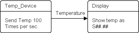
On Modbus you have a request/response protocol meaning Master send and wait for a Slave to respond.

On CAN all devices can send whenever they want using Arbitration. The 11 first bits in the header is arbitration field and basically the message with the lowest number “win”. This requires good timing and an aligned bus to work. The drawback is that the payload on classic CAN is 8 bytes. More modern bus systems like CAN FD and FlexRay that also uses arbitration have bigger payloads, but few MCU’s support these yet.

Modbus is a few messages and job done – it is a very simple protocol to wrap up.

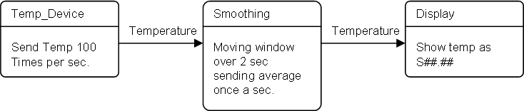
Modbus have high latency, while CANbus support burst – a technique to just send messages as fast as you can. The Burst technique more than compensate for the header and low payload – CANopen is far more efficient in data transfer than your would expect.

Modbus based on RS485 can support 2Mbps or 10Mbps serial lines, CANbus is max 1Mbps.

CANbus have a High Speed and Low Speed/Fault Tolerant version. The FT version means the transceiver can drop to half-duplex and continue to work with only one of the twisted pair wires as long as it also have Ground. The FT version is to my knowledge only used in SIIS2.

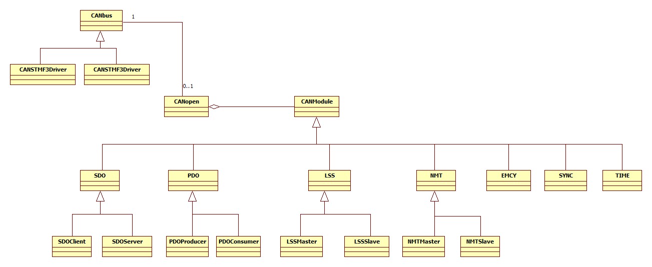
CANopen is a large job consisting of several components:

Bootlolader. This do not exist in Modbus, but CANopen have it’s own bootloader with a defined boot sequence where a device ask a Network Master (NMT) if it should start or download new firmware.

SDO is the main protocol to send generic data up/down. It support single variables and blocks of data both ways.

PDO allows you to send proprietary messages from node to node using all 8 bytes for data. SDO can only use 4 bytes, while PDO messages can be packed.

NMT (Network Master) perform start up sequence and monitor the network.

LSS (Layered Service Settings) consist of some 33 message sequences that control the node and its services.

And you also have the smaller components like Heartbeat, EMCY, SYNC and TIME.

The main part of a CANopen is however the object dictionary – which is similar to modbus registers. This is the list of objects and a huge portion of the CANopen standard is dedicated to describe how various devices should look like – what interface they should have.

CiA402 define a motor controller, while CiA443 define several standard Subsea components as examples.

The standards for CANopen have an extremely low quality – errors and inconsistent, little description to help understand usage etc – I have worked close to two decades with telecom protocols – actually writing protocols like ISDN and SS7 – and CANopen is the worst standard I have ever seen – it is a mess of a standard.

CANopen is NOT difficult as such, but understanding the so called standard in an uniform way and making sure devices integrate properly have turned out to be a lot of work.

Terminology like Master and Slave stack is used. CANopen have a few Master components, but it is actually a distributed network where some of the nodes takes on resposibilities. The work “Master” do however also means you have a device that is capable to track other devices – it need tables over the other devices etc, while a “Slave” or a “Device Stack” only need to know about itself.

For those new to CANopen I will recommend starting out with CANopenNode – this is open source C code under Apache 2.0 license. The stack is still work in progress, but I had no problem following some message sequences and noticing what was working correct/incorrect – which at the end means the code is mantainable.

Dark Theme in C#

Many modern applications use custom theme/styles, but this is actually far more difficult to implement than you would expect on Windows. Windows have a lot of standard GUI components where you can control most, but not all colors and styles. So, if you want dark theme you either need to buy a library or start making custom components that actually control all colors and styles. I decided to do the later. And while at it I also add new super components to make life easier. My objective is a dark theme not so unlike the one used in Visual Studio itself. I decided to code desktop apps in C# simply because Forms have improved their graphics and C# Forms is easy to work with.

This simple app is my component scratchpad showing some of the components I have made so far. You see small buttons, scroll bars, labels and edit fields. On bottom right you see a classic Windows combo box and as you can see I can’t control border colors yet. Looking at the edit controls (top right) I almost got it right using a standard component, but I could not control the border color. What I did was to use a edit component without a border inside a custom control where I override BorderStyle. I am realy pleased with this one because an edit text component is a bit of work.

The next control I had to work on was the tab strip. I have to modify the close cross a bit, but again it is a custom control with a small button and custom label component. As you can see I still have to do the menu and windows title fields on top – in fact I want to move the menu into the caption bar just like in Visual Studio to save space.

This is the beginning of my own Object Editor. I tried hard to avoid having to make this, but at the end I decided to jump into it. First of all this is a complex component as it is a simple grid with in-line editors and at the end it simply was to much that I could not control. But, having made the basic components properly it is easy to re-use them in a grid like this. I have not coded attributes properly so it just use reflection to grab a few edit fields for show yet.

This is a lot of work, but it is also fun. I want a proper HMI on my systems and I have made so much electronics that it is due time I start on the top-side part. C# also support Linux, Android and OSX. I actually ported a Forms application to Ubuntu once with just some minor changes. It will be a bit more work to port this HMI framework, but one step at the time. At this time I want to get the designer working and C# is the fastest way forward.

BasicPI Designers

UML is a well accepted standard for modeling complex software solutions, but it has never reached executable accuracy. The standard lack a technique that allow executable logic, which is exactly what PLD does. This is key to having a tool with 1:1 between diagrams and code.

I started modeling with Entity-Relationship Diagrams years ago, and these diagrams still have great value on physical database designs. ER diagrams are also a sub-set of class diagrams on the front-end, so they are easy to include.

HMI design is crucial if you deal with HMI. Starting this designer task I wanted dark-theme, and that means I have to take control of every HMI component to control colors anyway. Creating an HMI designer is on the front-end only about drawing symbols on the screen – far easier that the complex diagrams with rules.

Putting an ER designer and HMI designer together is alone a powerfully tool as you create database applications in seconds. This is what classic CASE tools used to focus on. Having this capability is nice, but only a side-effect of what I want.

PLD is a new technique combining two very popular techniques. Classic flow charts to express executable logic has been here since the beginning. SDL (Specification and Description Language) is still heavy used in telecom. PLD build on these two for graphical language and extend with techniques to have an executable specification. A diagram that in a few second describe what the logic is.

UML State Diagrams sneaked in because I liked the concept and it fills a gap between PLD and System Diagrams. PLD can be used for system diagrams, but state diagrams are more efficient.

As we also work in object oriented languages a class diagram is a must. This looks like an extension of a ER Diagram, but while a ER Diagram represent physical tables in a database (the actual container) a class diagram represent a definition of an object that needs to be declared – it is an advanced datatype. I use class diagrams heavy as I code in C++ and C#.

At the end we want to press a button and generate code. The concept is that you draw diagrams, press a button and your up running. But, it is good reasons why attempts on achieving this has failed in the past – lets see if it actually work this time!

Coding with UML State Diagrams

Some of you will remember that I planned a “System Diagram” in Plain! That was a block of configuration code that tied event on modules together. This is exactly what I plan to use UML State Diagrams for.

In this diagram we generate a Temp Changed event on one device that is sent to a Display on another device. UML State Diagrams are excellent for visualizing this event flow, but also capable to showing more detailed flow. What UML State Diagrams can not do is to visualize logic very well, so for that I use PLD or simply direct source code.

Lets forget about the internal logic in the two devices for now. We have one device that sample temperature 100 times per sec, a second unit that is capable of receiving and displaying temperature. The diagram simply say that as the temperature event is generated it will be sent to the display.

Temperature

  •             – time stamp
  •             – temperature

In this example we use easyIPC, so all the code we actually need is a “Wire” command at startup that is sent from “System Master” to Temp. Device:

  1. Look up address of Display Device
  2. Send Wire Temp_Device.Temperature to Display.TempInput

This will cause the Temp_Device to start sending Temperature messages 100 times a sec to Display. Now, sending temperature 100 timer per sec is a bit overkill, so we modify the diagram a little. In this case I add a smoothing function in. Smoothing is a pre-defined function in code, so all I need to do is to create the state and route temperature in and set smoothing Window to 2 sec with 1 sec output frequency. Smoothing is in effect average, so what this does is that we send the average temperature for the last 2 seconds every second.

Generated code will be something like this on the System Master at start-up:

  1. Look up address of Display Device
  2. Look up address of Smoothing function
  3. Send Wire Temp_Device.Temperature to Temp_Device.Smoothing.Input
  4. Send Wire Temp_Device.Smoothing.Output to Display.Tempinput

This example is highly simplified, but it illustrates top level UML State Diagram usage that can’t be covered that easily in other techniques.

BasicPI Designer – Dark Theme

Just showing a rude alpha version of the designer – I have yet to settle for a name I like. Notice the scroll bars on the diagram. Modifying Windows Scrollbar to dark theme is actually a bit of work.

Windows Controls always leave out a few bits you can’t control per application, so getting a dark theme is actually a lot of work. You basically have to take over ownership of all common controls and draw them yourself. But, for ScrollBar’s that was not an option as Paint was not called – I had to make my own from scratch.

I tried the same with the Windows Property Editor and it became so ugly that I decided to make my own here as well. But, a property editor on top of being forced to redo all common components are not so bad. And, yes it would have been less work to forget about dark theme for now, but I need to develope a proper dark theme anyway.

The designer include UML Class Diagram, Plain Logic Diagram and UML State Diagram so far. I intend to add a HMI Designer as well as a Proper Code Editor – the later is basically available for free as 3rd part component.

A lot of the work here is experimental, so I have to adapt as I go. PLD is a mature concept and UML Class Diagrams the same, but coding with UML State Diagrams is a bit new. As mentioned before it actually fit well together with source code or PLD.

And yes – it’s many errors in the visual diagram yet…

The concept here is that I will build a library to go on each embedded platform and then generate code towards that platform.

One important feature is that you can manually add support for existing code/source libraries. I might write an import for this, but the first version will be to define library interfaces in XML.

FlashForge Finder 2 Review

This costed me ca 400.- USD on a local shop, so I decided to try it out.

The first thing is the visual look. FlashForge Finder 2 looks like a furniture and can easily be placed in a living room or office.

One negative issue is the manual – it’s a bit short and it took a bit try and fail before I managed to remove all transport protections, after that it was only a few bottons and I was on my way to print my first test object.

Before you print anything you need to level the print bed. This was my first surprice as I realized that the printed had a level sensor and can direct the place leveling as well as deal with possible tilting or inaccuracy.

The second was loading the cartridge at the end and threading the needle – very straight forward.

As the printer start all I can say is that it is not exactly quiet – it also print very thin thread and is very slow compared to my first printer. But, wow – I do see the difference in quality on what comes out.

My biggest surprice was the Wifi connectivity and internal 18Gb storage meaning the printer can store what you print received from the network.


UML State Diagram

UML State Diagram is a standard, but I find it’s implementation into tools to be wage. So, I implement my own adaption because I intend to have a 1:1 with actual source code. This is not uncommon as most automation tools will have to make adaption in areas where executable accuracy is weak.

I was introduced to programming with UML State Diagrams through a different tool that I found to be of little use. But, it demonstrated the concept and I often use state diagrams so why not have one that actually is 1:1 with code on high level. A state diagram lack a lot of executable accuracy as it is only a high level diagram, but it does have some excellent qualities of showing event/signal driven flow on high level and as such accelerate overview of source code. The examples below are preliminary from an experimental tool.

The first symbol I use is the Entry point – a simple circle with a single output connection point (the red dot). All events inthese examples have the name “Hello”. The Red dot indicate that this diagram is illegal as a mandatory event is not connected.

This adds the Exit symbol and an event-flow between them showing a minimum, legal diagram. To draw this you first select the Entry/Exit symbols adding them, secondly you select Event Flow and draw a line between the 2 red dots. The dots dissapear as the events are connected. An output must connect to an Input etc.

The next is the State symbol itself. As you select a state you can chose between a generic sub-diagram, block of C++ code or premade component. All state’s will have a list of input and output events that at start will be displayed as Red or Green dots. Red dots represent abstract events that must be connected, while green dots represent virtual events that you can chose not to implement. Virtial events can also be hidden (tagged as ignored).

The dots will be replaced with lines and normal text as events are connected. The text “This is an example body..” will reflect the actual content – or by your choise a free text. The standard actually have a entry/exit notation – and I will need to do some adaptions on that.

This is a Fork where an event is duplicated and sent in parallell to two different states.

The opposite of a Fork is a Join that syncronize events.

As mentioned – this is an experiment, so I need to adapt as I go to develop the tool. The technique is not as mature as PLD and I am not sure about it’s actual worth, but I like the concept and want to see if this way of coding actually add value then done right and in combination with other techniques.

The tool itself needs a bit of work before its usable for anything and its an experiment as I complete the graphical editor that will be used for PLD as well.


UML Designer

Just showing a test diagram on the UML State Engine Designer I am making. It is stoll lots of work and details left, but progress is actually going fast the days I work on it. As for now this is just an experiment. A state engine can visualize some top level flow, but the details of the logic get hidden. My plan is however to let users chose between sub-state diagrams or code editors and see if that works out. It is regardless a cool tool even now.

The red dots are pre-defined events – input on left and output on right. Red means they need to be connected. As they are connected the red dot disapear and is replaced with the connection line. One trick on a diagram like this is to automate lines to avoid that users spend time making lines look nice.

Keep in mind that this is an automation tool that will generate source code, it is not a drawing tool. That said precentation of readable diagrams into doc is one of the objectives.

Interaction with source code and/or PLD is straight forward. PLD is excellent for visualizing logic and will handshake well wil State Diagrams.

Analogue Data Acquisition Hat

One of the big advantages with STM32 is that they have a range of MCU’s from the small M0 series to the more powerfully M7 series. Changing MCU to scale up/down is very easy. The MCU’s will have some differences in pin usage and register usage, but ST have been decently good at keeping their stuff as compatible as possible.

Pricing is another issue, buying through a distributor it is not that much difference between a M4 and M7.

The differences between these two are huge. H7 runs at 480Mhz, have 1Mb SRAM, 16 bit ADC channels etc. This is of no consequence if all you want to do is to blink a led. I have standardized on STM32F405 and that alone has far more power than I need for most parts.

STM32CubeIDE have also changed + H7 comes in a 100 pin package. The ADC channels combined with 1Mb SRAM and M7 opens for interesting data acquisition techniques so I have decided to try out the H7 on a Analogue Data Acquisition Hat. In fact I can use my existing nucleo to test out SW concepts, so I don’t need to start with HW in this case.