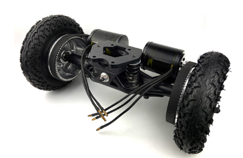
The wheels above are cool, specially since they can carry a lot of weight. But, the motors are 2 x 2.5KW and the belt driven design is very open making it easy to be contaminated. The powerfully motors are more designed for speed than for driving slowly, but I will optimize that later. Position system is straight forward, but expensive. I need 2 x ZED-F9P modules with 1cm satelite accuracy – the trouble is that these cost up to 200ich USD each. I have modules with lower accuracy that I will start working with as I also want to work on a non-satelite based position systems.
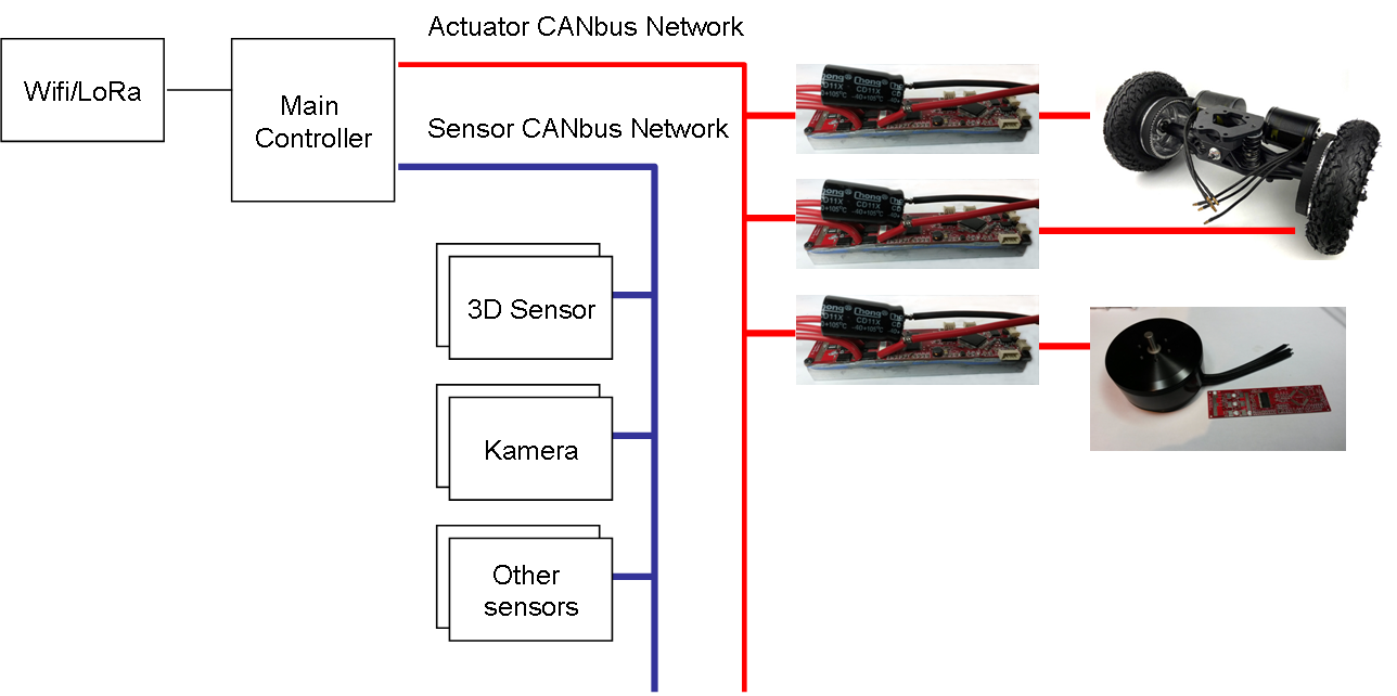
The diagram above is a schetch of the control system. I will be using an XportHub + Raspberry PI + LoRa board for main controller. It will be a modified version of XPortHub with 2 Galvanic issolated CANbus networks. The actuator network will use galvanic issolated drivers based on ISO1042 or similar – High Speed CAN. The sensor network will be isolated at the main controller, but not at the sensors. I have not illustraded power here, but actuators will have 18V supply while sensors have 5V. Three motor controllers as actuators – one for each wheel and one for the cutter. I will use a high speed propeller engine for the later.
So far this has just been a straight forward design based on available components. I just want to get the drive mechanism up running so I can start working on the position system. Building a lawn mower is just the start here – I have to admit that once I started this I was thinking “just for fun”, but the interest for what I do here + the wealth of ideas of what we can use this for is overwealming.
I still have to work a bit on my motor controllers before I start on the 3D sensor – the first objective is to just run this as a ROV outside so I can start on position reference as I test out infrastructure components.