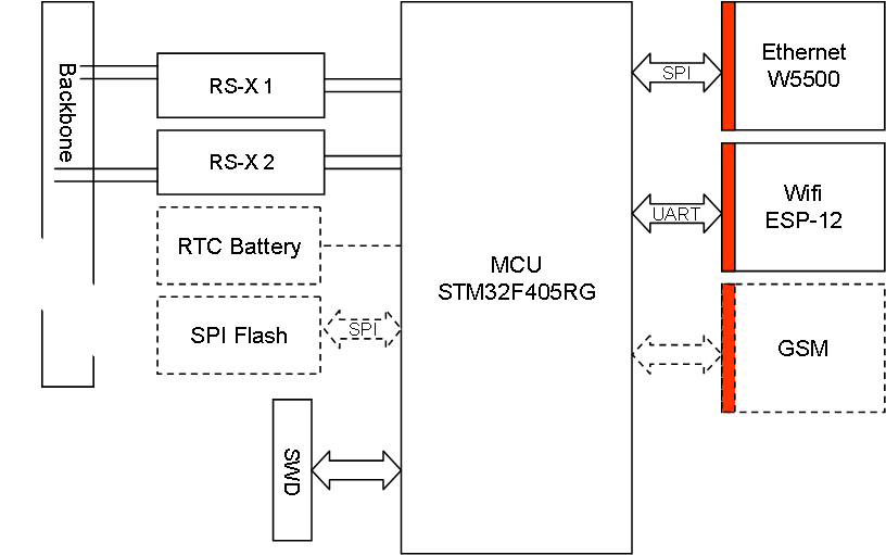
The block diagram above show the Ethernet module. Starting with a dual RS-X to the backbone and a SPI based W5500 for Ethernet connectivity. In addition we add a ESP-12 for Wifi, SPI Flash for storage and a RTC battery & oscillator as well as the mandatory SWD connector. I hope to have a 3D model of this board ready within the next days. The red box on Ethernet/Wifi mark that this is galvanic isolated.
The STM32 design will differ from earlier designs as I will be using x-tal’s with higher quality and add the RTC x-tal as well. I am toying with the idea of testing a supercap as “battery”. A normal battery has a degrading over time that forces it to be replaced on regular basis. As a RTC battery only need to survive a power down for some time it could be interesting testing a supercap as an option. It is also an option to dedicate one of the available pin’s on the backbone to “Power off battery” and use wakeup functionality on the MCU.
I have also drafted a GSM as optional add-on here. As this will be an external breakout it might make sense to add it to this module rather than creating a separate one. This is however something I need to look into. At present I have little experience using GSM like this.
The RS-X backbone speed will probably be 2.5Mbps, both lower and higher speeds are an option.