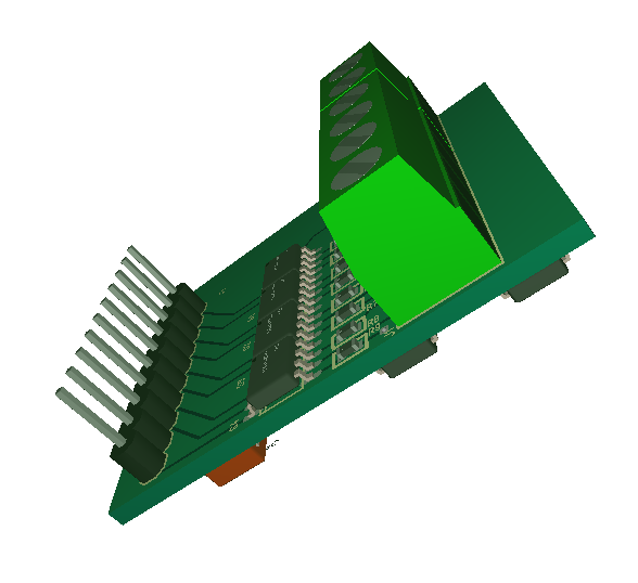
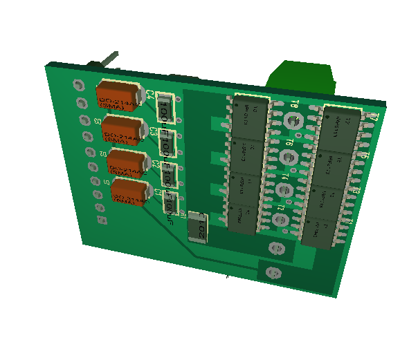
This is a 4 x half bridge driver with a current sensor. I decided to create a pure driver board because I intend to destroy these in testing to learn it’s actual capacity. I don’t want a MCU mounted on things I expect to be overheated. It is at the same time a bit cool to have the driver step separate for DIY projects. The second layer with the high current PCB lanes are shown below. This is quite small ca 35 x 35mm. The PCB’s take ca 6 weeks so I won’t get them before mid January 2017.
 As mentioned before this takes 30V and 17A @ 70 degrees. The datasheet gives higher rating and yes we can draw more for a short time, but I want to know how much I can draw continuously with a heat-sink mounted and keeping an acceptable temperature. I expect the actual capacity to be a bit below the datasheet for the HEXFET’s.
As always – this is a draft. I am considering adding a few things, but will think about that through the weekend.